Saturday, 14 December 2019

ACI + UCS: Two ships finally meet

Simplicity has become the new mantra within IT, especially within the datacenter. An abstracted intent driven policy model is the foundation to achieving simplicity. Cisco pioneered this concept back in 2009 with the release of UCS, introducing a radical shift in how compute services are delivered. The desired compute need can be described in an abstracted policy model and automatically orchestrated across a unified compute fabric (compute/peripherals/storage/network).

Cisco ACI, Cisco UCS, Cisco Tutorial and Material, Cisco Certifications, Cisco Online Exam, Cisco Study Materials

ACI brought a similar intent driven model to the datacenter networking fabric. Users can model their ideal network topology in a very simplistic user interface and that policy is delivered across a very sophisticated VXLAN host-based routed fabric. ACI automates complex tasks like creating VRFs consistently across a fabric, setting up anycast gateways on all leafs, configuring the underlay and overlay routed networks to support a VXLAN topology, extending networking and security policies across physical sites or into the cloud, and much more.

And now the problem


One very common and popular use case for ACI is managing network segments for workloads to consume, especially for hypervisor based workloads. In the past, the process of properly plumbing a network segment all the way down to the virtual switch required coordination across multiple teams. Network operators needed to ensure the VLAN was properly defined upstream, routing was configured for that network, and the VLAN was trunked across all switches where needed. The hypervisor operators would then need to ensure the same VLAN id was configured properly within the virtual switch across all hypervisor hosts where needed. If any of the hypervisor hosts lived in a blade enclosure where vendor specific networking elements were used then the server operating team would also need to ensure the VLAN was configured properly through the blade switching fabric.

With all of these potential touch points, the theoretically simple task of extending a new networking segment to virtual workloads could be very error prone and susceptible to lengthy delivery times…….but there’s a much simpler way…..ACI to the rescue!! With ACI, the delivery of this network segment can be fully delivered to the virtual switch with multi-tenant segmentation included. This takes care of the physical and virtual networks however server enclosure switching would still need to be configured properly by the server operations team. While UCS provides a programmable compute fabric which makes creating these VLAN segments simple and consistent, operationally ACI and UCS were ships in the night completely operated by different teams thus requiring a coordinated effort.

Better Together FTW


With the 4.1.1 and above release of ACI these two ships have joined forces to completely remove the operational overhead!! For the remainder of this post we will look at how VMM integration is configured inside of ACI, how we had to separately configure UCS in the past, and how this new ACI+UCS integration makes the task simpler.

VMM integration with ACI


Integrating ACI with a VMM (virtual machine manager) domain such as vCenter is very easy to do using the ACI UI. Please watch the video below for a detailed walkthrough.


Testing Connectivity: First Attempt


At this point ACI has helped automate the delivery of multiple multi-tenant network segments (EPGs) throughout the physical and virtual networks. Now let’s attach some linux test VMs to these new networks and verify connectivity.

Centos VM 1

Cisco ACI, Cisco UCS, Cisco Study Materials, Cisco Tutorial and Material, Cisco Online Exam

Cisco ACI, Cisco UCS, Cisco Study Materials, Cisco Tutorial and Material, Cisco Online Exam

Centos VM 2

Cisco ACI, Cisco UCS, Cisco Study Materials, Cisco Tutorial and Material, Cisco Online Exam

Cisco ACI, Cisco UCS, Cisco Study Materials, Cisco Tutorial and Material, Cisco Online Exam

From within the vCenter web console for demo-centos-1 we can check if an IP address was properly allocated via DHCP.

Cisco ACI, Cisco UCS, Cisco Study Materials, Cisco Tutorial and Material, Cisco Online Exam

It appears that our test vm did NOT properly receive an IP allocation from the DHCP server. What went wrong?

ACI has handled configuring the network segment through the physical and virtual fabric but what about server networking within the UCS compute fabric? Let’s investigate.

Cisco ACI, Cisco UCS, Cisco Study Materials, Cisco Tutorial and Material, Cisco Online Exam

As shown above, one of the dynamic VLAN IDs (1005) was checked out of the pool created in ACI and assigned to the distributed port group our test VM is using. However, inside of UCS Manager the VLAN list for the vNIC template of the ESX host is blank. This would definitely explain why reachability is broken.

Cisco ACI, Cisco UCS, Cisco Study Materials, Cisco Tutorial and Material, Cisco Online Exam

Now let’s add VLAN 1005 to the UCSM VLAN definitions as well as to the vNIC template and re-test.

Cisco ACI, Cisco UCS, Cisco Study Materials, Cisco Tutorial and Material, Cisco Online Exam

Cisco ACI, Cisco UCS, Cisco Study Materials, Cisco Tutorial and Material, Cisco Online Exam

The test vm now successfully negotiates a DHCP address and is able to ping its default gateway. Rinse and repeat this process for the second EPG.

Cisco ACI, Cisco UCS, Cisco Study Materials, Cisco Tutorial and Material, Cisco Online Exam

Cisco ACI, Cisco UCS, Cisco Study Materials, Cisco Tutorial and Material, Cisco Online Exam

In the past, you could minimize this operational overhead by pre-populating all of the VLANs from the dynamic VLAN pool in ACI into UCSM. The drawback to this approach is you are creating unnecessary overhead (STP logical ports) for network segments that may not be in use.

A Better Approach


With the release of ACI version 4.1.1 and above, a new capability has been added called Cisco ACI with Cisco UCSM integration. Today, this integration is specifically for VMM domains deployed on an FI-based UCS compute fabric. The following pre-requisites are required for this new integration to work:

◉ Cisco Application Policy Infrastructure Controller (APIC) Release 4.1(1) or later

◉ Cisco UCS and Cisco UCSM properly installed and configured in your data center

◉ Cisco UCSM 3.2 or later

◉ UCSM vNIC templates that are configured as Updating Template type

◉ Creation of a VMware VMM domain or a Microsoft System Center Virtual Machine Manager (SCVMM) domain (vCenter example is shown in the first part of this blog)

◉ Installation of the Cisco External Switch app.

Setting up the Integration

1. Ensure you’ve met the pre-requisites listed above

2. Install the External Switch ACI app and configure the UCSM Integration


3. Create a new EPG

Now that the integration setup is complete let’s create a new EPG and see how things have changed operationally. Back in the ACI user interface we can repeat the procedure from Step 3 in the VMM Integration with ACI section to create a third EPG.

Cisco ACI, Cisco UCS, Cisco Study Materials, Cisco Tutorial and Material, Cisco Online Exam

Cisco ACI, Cisco UCS, Cisco Study Materials, Cisco Tutorial and Material, Cisco Online Exam

Now we can verify that the new port group was created on the ACI managed VDS.

Cisco ACI, Cisco UCS, Cisco Study Materials, Cisco Tutorial and Material, Cisco Online Exam

As shown in the screen capture above, ACI assigned VLAN 1004 from the dynamic pool to the newly created port group mapped to our EPG. This is where the wheels fell off previously because the VLAN was not yet defined within the UCS fabric. We can now go back into UCSM to verify.

Cisco ACI, Cisco UCS, Cisco Study Materials, Cisco Tutorial and Material, Cisco Online Exam


Cisco ACI, Cisco UCS, Cisco Study Materials, Cisco Tutorial and Material, Cisco Online Exam

In the screen captures above we can see that VLAN 1004 was correctly added to our VLAN Group managed by the ACI+UCS integration and was also added to our VNIC templates for the ESX hosts. Now we can assign another test VM to this newly created port group and test connectivity.

Cisco ACI, Cisco UCS, Cisco Study Materials, Cisco Tutorial and Material, Cisco Online Exam

Our test VM was successfully assigned a DHCP address and is able to ping our first test vm in the 172.17.0/24 subnet.  Mission accomplished!!!

But what about cleanup???


The ACI+UCS integration connects the dots between ACI and UCS for creating new EPGs within our VMM Domain but what about teardown?  Simple enough to test, let’s delete the EPG we created in the last section.

Cisco ACI, Cisco UCS, Cisco Study Materials, Cisco Tutorial and Material, Cisco Online Exam

Validating in vCenter

Cisco ACI, Cisco UCS, Cisco Study Materials, Cisco Tutorial and Material, Cisco Online Exam

Validating in UCSM

Cisco ACI, Cisco UCS, Cisco Study Materials, Cisco Tutorial and Material, Cisco Online Exam

From the screen captures above we can see that the port group was properly removed from the VDS in vCenter AND the VLAN was also removed from the VLAN group and VNIC templates in UCSM.

Final Thoughts


If simplicity is the ultimate goal then the ACI+UCS integration helps get you that much closer to the finish line.  Together these two solutions provide intent driven policy models that simplify how network and compute services are delivered within your datacenter anywhere environments.

Friday, 13 December 2019

The Power of Multi-Domain Integration for Your Network

Cisco Enterprise Networks, Cisco Guides, Cisco Tutorial and Materials, Cisco Learning, Cisco Certifications, Cisco Online Exam, Cisco Study Materials

End-user expectations for digital experiences have never been higher. Cisco is meeting the demand to have an unplugged and uninterrupted experience with its multi-domain integration across the data center, campus, and branch.

Cisco Enterprise Networks, Cisco Guides, Cisco Tutorial and Materials, Cisco Learning, Cisco Certifications, Cisco Online Exam, Cisco Study Materials
But what does this mean in practicality? Application access must be secure regardless of location. Everything must be connected. And the connection must always be on. These expectations are driving the digital transformation happening all around us today.

Today’s workforce is mobile, unplugged, and expects a high-quality application experience, The office is wherever you are, whether it be in the office, at home, or at a café. Such connected mobility is critical, but how well you’re able to interact with your applications is perhaps even more critical for productivity.

For businesses, the need for user segmentation is growing, while also ensuring a completely secure environment. Businesses must provide what users have come to expect when it comes to infrastructure availability, flexibility, and performance. Every organization needs to deliver this unplugged and uninterrupted experience. Business outcomes are driven by connected devices that must be always-on. Network downtime means missed opportunities and the halt of growth.

Finding the right balance


The challenge of balancing these requirements for an unparalleled digital experience falls on the shoulders of IT. When considering how varying the types of needs in different campus environments are today, you can understand the need for multi-domain integration that brings together network visibility, access, and always-on security:

◉ Medical campuses, with life-saving devices connected and relying on the network.

◉ Facilities management, with a vast array of IoT that includes HVAC, security imaging, and lighting control systems.

◉ Retail operations, with internet-connected robotic systems fulfilling orders and restocking returns.

Marriott’s 2018 data breach is the perfect example of the delicate balance between user experience and security that IT must manage. While the focus was on users and the ease of its reservation-booking experience, the hotel chain was unaware that a security breach in the reservation database had taken place over a four-year period, which involved over 380 million guest records and cost the organization more than $120 million to mitigate.

On the one hand, IT is tasked with providing the best digital experience for users and the organization. But at the same time, an equal importance must be placed on compliance requirements and mitigating business risk.

Multi-domain integration for your network


In response to this need, Cisco introduced Intent-Based Networking (IBN) in 2017, which delivers a secure, end-to-end digital experience, with its intuitive, self-optimizing, always-secure network that takes the guesswork out of network management through the power of multi-domain integration.

Cisco Enterprise Networks, Cisco Guides, Cisco Tutorial and Materials, Cisco Learning, Cisco Certifications, Cisco Online Exam, Cisco Study Materials

For the campus, Cisco has delivered the IBN vision through SD-Access. For the branch, it’s SD-WAN. And our Application Centric Infrastructure (ACI) encompasses both the data center and cloud. Multi-domain integration enables these three components to complete our IBN vision, which is a solution only Cisco can provide.

Enhancing your business outcomes, multi-domain provides the expected user interactions with all applications across these interconnected domains, while simultaneously driving down costs, complexity, and risk.

Users and devices can log on from anywhere, while applications can also reside anywhere. Whether you’re using cellular, wireless, or a wired connection from any campus, branch, or remote location, the end-user is provided a seamless, secure experience regardless the means of connection.

The support of built-in security


Built-in security is a key component to reducing the attack surface and mitigating risk, while continuing to provide a fully connected, uninterrupted service. And there are three fundamental pieces of the end-to-end security that multi-domain integration provides.

The first is continuous network visibility. Traditional perimeter-based security, or even a standalone endpoint security solution, isn’t able to address the network communications flow between users, applications, and devices.

Next is Zero Trust. Bad actors are becoming more sophisticated in avoiding detection. Logical end-to-end segmentation—where we contextually group all endpoints, users, devices, and applications—enables the network to isolate only those assets and resources where access is authorized at any given time.

Finally, constant protection is the final piece of our security puzzle. The network transformation afforded by multi-domain integrated architecture means your entire infrastructure becomes dynamic. To provide total security, Cisco embeds hundreds of thousands of control points with every network device—from the campus across the branch, and into the data center and cloud.

Multi-domain integration brings all the pieces of the IBN puzzle together. And Cisco invites you to unlock the potential of your network and take the next step in your organization’s digital transformation.

Watch for a future blog that dives deeper into the multi-domain integration story and how it works for your network.

Thursday, 12 December 2019

ONE Silicon, ONE Experience, MULTIPLE Roles

Cisco Study Materials, Cisco Tutorial and Material, Cisco Guides, Cisco Learning, Cisco Study Material, Cisco Online Exam

Wherever you are, you likely have devices containing a semiconductor chip around you – computers, phones, television sets, printers, cars, trains, airplanes, and more. It’s almost hard to believe that this tiny electronic component unleashed the same magnitude of change as the Industrial Revolution by making the computer revolution and the digital age a reality. And these semiconductor chips are everywhere; today, there are more chips in existence than people on earth.

As a critical building block of networking devices, silicon chipset design primarily addressed routing use cases, and chipsets were optimized for programmability, deep buffering, and scale. When enterprises and cloud providers needed higher bandwidth, silicon designs emerged optimized explicitly for high-bandwidth and low power consumption. They met an immediate need, but at the expense of programmability, buffering, and scale.

Cisco Study Materials, Cisco Tutorial and Material, Cisco Guides, Cisco Learning, Cisco Study Material, Cisco Online Exam

Different silicon chipset requirements pushed the industry down a trajectory of two separate markets – the switching and routing markets – each of them defined by unique architectures, systems, and software. Despite several attempts to converge these into a single architecture, they have remained separate. Until today, switching silicon has always been faster than routing silicon.

While the industry searched for a convergence point, it grappled with the slowdown of “laws” that governed the development of silicon chipsets. For decades, the economics of silicon have been guided by 1) Moore’s Law – the number of transistors on a single silicon chip would double every two years and 2) Dennard Scaling’s Law – as transistor dimensions shrank, each transistor would operate faster and use less power. These two laws drove the golden age of silicon chipsets, but they are showing signs of weakness. As a result, silicon designs – for both routing and switching – have diverged as companies tried to overcome the limitations of Moore’s and Dennard’s Laws in their own way.

As innovators, and despite the mounting challenges, we never stopped dreaming of a single chipset architecture that could serve the needs of routing and switching. Could we build one architecture to solve multiple market needs, form factors, roles within the system, and that could scale, as needed? And could we do it all without making any compromises?

If we could build it, it would mean a fundamental shift in the industry.

Today, I’m thrilled to announce Cisco Silicon One™- a ground-breaking, new silicon architecture that has achieved these lofty goals.

For the first time, not only are we elevating routing silicon’s performance to the same level as switching silicon’s performance – both from a bandwidth and power efficiency perspective – but we are also paving the way to faster performance gains in the near future.

Cisco Silicon One is the first architecture that serves several different market segments – service provider and web-scale. And with future product lines built on a consistent silicon architecture, customers can enjoy ONE experience across the entire network, across all network functions and covering all form factors. With Cisco Silicon One, customers can significantly reduce OpEx – as network engineers save time on testing functionality, qualifying new hardware, and deploying new services with greater consistency and faster time-to-market.

Cisco Silicon One Q100, the first generation of this architecture, is twice the network capacity of all other high-scale routing ASICs. It is the first routing silicon to break through the 10Tbps benchmark for network bandwidth, without compromising carrier-class capabilities, e.g., feature richness, large queue set, deep buffers, large NPU tables, and advanced programmability.

It also demonstrates many architectural advantages. It can support a fixed switch or router with 10.8T worth of network ports up to large non-blocking distributed routers with Petabit scales. All of them with non-blocking performance, deep buffering with rich QoS, and programmable forwarding.

Another important innovation of the Cisco Silicon One Q100 is its unprecedented versatility. Up until now, networking vendors were using different and specific silicon chipsets for standalone processors, line card processors, and fabric elements.

But with the Cisco Silicon One Q100, all of these roles, including standalone network processor (optional deep buffers), traditional line card network processor (optional deep buffers), oversubscribed line card network processor (optional deep buffers), and fabric element in a distributed router can be met by a single chipset. All accomplished with a common and unified P4 programmable forwarding code and SDK.

Cisco Study Materials, Cisco Tutorial and Material, Cisco Guides, Cisco Learning, Cisco Study Material, Cisco Online Exam

And networks built with Cisco Silicon One Q100 will deliver greater consistency in features, services, and telemetry across multiple network locations because it unifies and streamlines operations by eliminating parity problems, upgrades, and other issues associated to different silicon.

The innovations in Cisco Silicon One represent years of investment and are vital for the future of the Internet. Legacy designs that rely simply on CMOS densities will suffer from the slowdowns inherent in Moore’s Law. With Cisco Silicon One, Cisco opens up a fast lane to future innovation that will outpace traditional methods while development cycles for silicon iterations will be dramatically shorter.

Wednesday, 11 December 2019

Drag and drop your way to network segmentation

I can understand if you dread configuring network segmentation. Not only is it hard to configure the many different switches and routers, creating VLANs, using ACLs to create lists of permit or deny IP addresses, it is also easy to make mistakes and risk shutting down parts of the network. And with users and devices moving around, you must continuously modify these configurations. Is it any surprise that many of today’s networks are not optimally segmented?

In this blog we discuss how Cisco Digital Network Architecture (Cisco DNA) makes it easy to segment your campus and branch networks. This blog is the second in a series focusing on aspects of intent-based networking, the first being on controller-led architecture.

Before digging into the solution, let’s understand why you may want to segment your network in the first place.

Cisco Study Materials, Cisco Tutorial and Material, Cisco Guides, Cisco Certifications, Cisco Learning

◉ Enhanced security: Isolate and filter network traffic to limit communications between users and devices

◉ Better access control: Allow users and devices to access only authorized resources

◉ Improved monitoring: Log events, monitor connection attempts, and detect suspicious behavior

◉ Faster containment: Minimize the scope of a network breach


Group-based access control


Recognizing that segmenting the network is a security must-have, we set about making it easy to do in Cisco DNA – the access network for campus and branch. Those of you who have experienced the Cisco DNA Center – the controller for a Cisco DNA based network – know that it provides a highly intuitive and easy to use graphical interface to manage the network and is the ideal platform to define segmentation. For those who haven’t, we encourage them to attend one of our monthly demo sessions where we explain what Cisco DNA can do for you.

Cisco DNA Center allows you to easily manage security policies through policy-based abstractions called scalable groups.  Scalable groups are used to represent connected users and devices based upon attributes, like role, function, location, etc. rather than IP addresses. These groups then form the basis of security policies, centrally managed on Cisco DNA Center and enforced across the network fabric.

Cisco DNA Center enables simplified management of access control between the different groups, and dynamically configures the access control policy in the fabric consisting of switches, routers, and wireless network devices that make up the fabric.

As people and things connect to the network using either a wired or wireless interface, Cisco DNA identifies them and automatically assigns them to their rightful group and places them in the appropriate segment. We call the creation of these Virtual Networks (VN), macro-segmenting.

The two levels of network segmentation


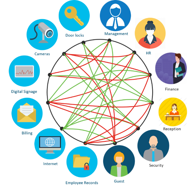
But what about the communications between members within a VN? We need to control that too for a deeper level of security. We call this micro-segmenting. So, while macro-segmenting isolates traffic between VNs, micro-segmenting controls communications between different groups or members of the same group within the VN.

For example, you might define two VNs – an ‘Employee’ VN with management, HR, security staff, and financial analysts, and an ‘IoT’ VN with security cameras, door locks, and digital signage. With SD-Access macro-segmentation you can ensure that a compromised camera will not let the attacker access HR resources. While with micro-segmentation, you can prevent lateral spread of malware between say HR and security staff or between two financial analysts.

Cisco Study Materials, Cisco Tutorial and Material, Cisco Guides, Cisco Certifications, Cisco Learning

Cisco DNA Center makes it easy to micro-segment the network. The Access Control Application within Cisco DNA Center works with Cisco Identity Services Engine (ISE) to let you define contracts. Contracts are statements that permit or deny specific types of interactions. For example, if you are concerned about malware attacks that spread using well-known TCP ports of 22, 80, and 443, you can simply create a contract that would disallow such communications between members of the same group.

Once you define the contracts, you use a simple matrix within Cisco DNA Center and activate them between source and destination groups. This matrix visually describes policies that the Cisco DNA Center consistently applies and enforces through the network fabric.

Segmentation that extends from access to apps


Just like Cisco DNA Center segments the access network and creates groups of users, Cisco ACI segments data center and cloud networks and creates groups of applications. Cisco’s multidomain architecture lets these networking domains exchange and map these groups. Now, thanks to this integrated segmentation, users can only run applications they are authorized for. For example, only accounting staff may access point-of-sale systems in keeping with PCI regulations.

Tuesday, 10 December 2019

How Wi-Fi 6 overcame one of the toughest wireless environments on the planet

Metal and heat. Since ancient times, these two foundational elements have continuously been used to create a variety of tools. In medieval times, metallurgy technology spawned swords and armor unlike any before it and, in the early 19th century, it vitalized the Industrial Revolution. Nowadays, high-tech metallurgical processes are giving rise to advanced materials and products.

In today’s industrial plants, manufacturers are streamlining processes to create better products, free of defects, that meet exact tolerances. Mettis Aerospace has been at the forefront of metallurgical innovation for over 80 years, specializing in forging, machining and sub assembly for the aerospace and defense sectors. The company uses powerful presses to forge a variety of metals into highly sophisticated products for the aerospace industry. As a technology driven company, Mettis also relies on network connected sensors, cameras, and robotics to manufacture their products. This is where Cisco, its technology, and partnerships comes in to play.

Electromagnetism and Wi-Fi


Cisco Study Materials, Cisco Guides, Cisco Tutorial and Material, Cisco Certifications, Cisco Online Exam

While metal and heat are needed for the forging of aerospace products, they are also detrimental to Wi-Fi. As a conductor of electricity and magnetism, metal directly affects radio waves, including those from Wi-Fi. This means that in a building made mostly of steel, where people are working with various metals on massive steel and iron presses, such as Mettis’ forging facilities, radio waves are reflected and diffracted in all directions. More metal means more degradation and interference, resulting in an unacceptable Wi-Fi experience. Add in high-heat (1000+ degrees Fahrenheit) and its effect on the electrical equipment and you have the worst possible situation for Wi-Fi.

Interesting fact: Mettis is home to some of the most powerful forging presses in the UK, one in particular weighs the equivalent of over 200 small cars.

Wi-Fi 6 drives industrial applications with ease


With that in mind, Cisco, along with its partners from the Wireless Broadband Alliance, set out to test Wi-Fi 6 at the Mettis manufacturing plant in Midlands, England. For the above reasons, previous attempts to use Wi-Fi failed in this environment. However, with Wi-Fi 6 come new technologies that enable it to perform in less than optimal conditions.

◉ First and most important, Wi-Fi 6 offers a new radio channel structure, allowing narrower but longer data symbols. Additionally, flexible orthogonal frequency division multiplexing (OFDM) guard interval ensures that Wi-Fi signals do not interfere with one another and cause overlapping transmission issues. This longer symbol duration (Ts) and guard interval (Gi) is better able to resist harsh multi-path environments, such as those found in the Mettis plant.

◉ Second, OFDM access (OFDMA) multiplexes multiple users on the same channel at the same time increasing network efficiency and providing lower latency for both uplink and downlink traffic. This is important for business critical, delay-sensitive applications used in manufacturing environments.

◉ Third, WiFi6 offers significant co-channel-interference (CCI) mitigation via Basic Service Set (BSS) color techniques that allow the operator to selectively ignore interference; boosting reliability and reducing delay. This is critical in open-space high-ceiling environments such as those found in the Mettis plant.

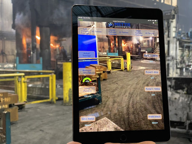
Mettis tested 4k live streaming video from cameras mounted on robotic arms, augmented reality to support equipment status and repairs, large file uploads, and Wi-Fi video calling on smartphones. Cisco Catalyst 9100 Wi-Fi 6 capable access points met all trial expectations with very low latency across a variety of partner devices throughout the manufacturing floor to prove out the success of the technology. Speeds reached 700Mbps which was our benchmark for this trial using the 80Mhz channel. Future trials will include the 160Mhz channel with a benchmark of gigabit speeds.

This was a huge success for all, especially Mettis. The pilot highlighted that industrial applications go beyond typical use cases and require the latest Wi-Fi 6 technology at both the network and device level to ensure consistent and reliable access and connectivity.

Cisco Study Materials, Cisco Guides, Cisco Tutorial and Material, Cisco Certifications, Cisco Online Exam

Sunday, 8 December 2019

Putting the Enterprise in the 5G Driver’s Seat

Cisco Study Materials, Cisco Guides, Cisco Learning, Cisco Online Exam, Cisco Tutorial and Material

The enterprise offers boundless opportunities as we move into and through the 5G era. 90% of Service Provider CXOs said the most important new revenue streams in 5G are going to come from enterprise.

But what are the business models for 5G where the enterprise is concerned? And did anyone actually ask the enterprise if they’re even interested in 5G?

We did and they are. Cisco surveyed our enterprise customers and asked them what they wanted to receive from a 5G experience, and these are just some of the things they told us they expect:

· More flexibility, control and visibility from their Service Providers.
· A network that’s easy to operate and deploy.
· The ability to drive their network, based on policy (intent-based networking).

Wi-Fi 6 or 5G?


Cisco Study Materials, Cisco Guides, Cisco Learning, Cisco Online Exam, Cisco Tutorial and Material

So, does the enterprise want Wi-Fi 6 or 5G? Is it a binary decision? The answer that came back from our enterprise customers is that they want the right tool for the job, whatever the job may be. We’ve been working to break down the characteristics of each access type to understand what the right tool is for each job, so that we can advise our enterprise customers accordingly, and put them on the road to success.

Enterprises are digitizing completely, and new applications will require pervasive compute and connectivity. On one hand, Wi-Fi 6 offers mass availability, less cost and ease of deployment. On the other, 5G is stronger in terms of handoffs, low latency and determinism.

To enable the enterprise to capture new revenues, we’re putting them in the driver’s seat with bundles, verticals and new channels. In some places, Wi-Fi 6 makes sense. In others, 5G is the right tool for the job. Often, the enterprise will benefit from both technologies. It all comes down to the specific needs in a given vertical, the associated policy and service requirements, and how we package the services and bring them to market in new and intelligent ways. This service creation, combined with our unmatched end-to-end portfolio, makes Cisco the most important 5G vendor out there.

Saturday, 7 December 2019

Configuring Cisco Security with Amazon VPC Ingress Routing

Today, Amazon Web Services (AWS) announced a new capability in Virtual Private Cloud (VPC) networking that is designed to make it easier and more efficient for Cisco Security customers to deploy advanced security controls in the cloud. This new capability is called Amazon VPC Ingress Routing. It allows users to specify routes for traffic flowing between a VPC and the internet or from a VPN connection, such as a private datacenter.

Amazon VPC Ingress Routing is a service that helps customers simplify the integration of network and security appliances within their network topology. With Amazon VPC Ingress Routing, customers can define routing rules at the Internet Gateway (IGW) and Virtual Private Gateway (VGW) to redirect ingress traffic to third-party appliances, before it reaches the final destination. This makes it easier for customers to deploy production-grade applications with the networking and security services they require within their Amazon VPC.

While the remainder of this post focuses on Cisco’s NGFWv and ASAv products, this capability can also be used to deploy a number of other network-based security solutions into the AWS traffic path. This includes services such as the following:

◉ Firewall policy enforcement
◉ Network traffic visibility
◉ Malware detection
◉ URL filtering
◉ Intrusion Prevention
◉ DNS security

This is a big win for Cisco customers deploying our security products in AWS, and we are pleased to have been an early adopter and Integration Partner with AWS on this launch.

How to Use Amazon VPC Ingress Routing with Cisco Firewalls


The configuration is achieved by creating a custom route table and associating subnet routes with the private Elastic Network Interface (ENI) of the security appliance, and then associating the public ENI with an IGW and VGW. A single firewall instance can protect multiple subnets; however, a separate instance is needed per VPC. Below are some details on the testing we performed as well as sample use cases and configuration guidance.

Use Cases / Deployment Scenarios


Cisco NGFWv/ASAv can be deployed in a VPC to protect the following traffic flows:

◉ Traffic Traversing an Internet Gateway (IGW) To/From the Internet
◉ Traffic Traversing a VPN Gateway (VGW) To/From a Remote VPN Peer

Benefits of Using Amazon VPC Ingress Routing with Cisco’s NGFWv and ASAv


◉ Offload NAT from the firewall to AWS network address translation (NAT) gateway or instance
◉ Simplify protection of multi-tier applications spanning subnets and VPCs
◉ The scalable design makes it easy to add new subnets, and more of them
◉ Enables bi-directional, threat-centric protection for traffic bound for private networks and the internet

POC Deployment Scenario


Enable outbound Internet connectivity and offload NAT function to AWS NAT gateway

In this scenario, the Cisco Firewall (NGFWv or ASAv) is deployed between internal services in the AWS VPC and the internet. The route table for the Internet Gateway (igw-rt) has a specific route for the Inside subnet which directs inbound traffic to the Cisco Firewall for inspection. Prior to this enhancement, the users had to NAT egress traffic on the firewall to bring back the reply packet to the same virtual appliance. This new configuration eliminates the need for an ENI on the firewall and removes the requirement to perform NAT on the firewall, thus improving performance.

Cisco Security, Cisco Learning, Cisco Tutorial and Material, Cisco Guides, Cisco Online Exam

Cisco NGFW/ASA with AWS IGW (routable attached to IGW) and AWS NGW to NAT outbound traffic

Cisco NGFW/ASA with Multiple Subnets, Three-tier Architecture Using IGW and Amazon VPC Ingress Routing

This topology expands on the previous​, demonstrating how multiple subnets can be protected by a single firewall. By utilizing the AWS NAT Gateway service, the number of protected subnets behind a single firewall can be scaled significantly beyond what was previously possible.

As with the previous architecture, the ​Cisco Firewall is deployed at the edge in routed mode, forwarding outbound traffic to the IGW. Multiple routes are configured in the IGW’s route table to direct the traffic back to the appropriate subnet while the protected subnets forward their traffic to the internal firewall interface via the NAT gateway.

Cisco Security, Cisco Learning, Cisco Tutorial and Material, Cisco Guides, Cisco Online Exam

Cisco NGFW/ASA three-tier Architecture with AWS IGW and VPC Ingress Routing

Cisco NGFW/ASA with Multiple Subnets, Three-tier Architecture Using VGW and Amazon VPC Ingress Routing 

Cisco Firewalls can also be deployed in an Amazon VPC to inspect traffic flowing through a VPN tunnel. In this case, the ​Cisco Firewall is deployed at the edge in routed mode, forwarding outbound traffic to the to a VGW. In this example, the local and remote networks are routable; therefore, the NAT gateway can be eliminated, further improving efficiency and reducing cost.

Cisco Security, Cisco Learning, Cisco Tutorial and Material, Cisco Guides, Cisco Online Exam

Cisco NGFW/ASA three-tier Architecture with AWS IGW and VPC Ingress Routing

In Addition to Support for Amazon Ingress Routing, we are adding AWS Security Group management to Cisco Defense Orchestrator (CDO). We are also extending the existing ACI policy-based automation for L4-7 services insertion to the AWS cloud by leveraging Amazon VPC ingress routing. These integrations will make deploying L4-7 services in a hybrid cloud as well as Cisco Security at scale in AWS easier than ever.