Tuesday 29 March 2022

Hyperconverged Infrastructure with Harvester: The start of the Journey

Cisco Exam, Cisco Exam Prep, Cisco Exam Preparation, Cisco Learning, Cisco Career, Cisco Certification, Cisco Skills

Deploying and running data center infrastructure management – compute, networking, and storage – has traditionally been manual, slow, and arduous. Data center staffers are accustomed to doing a lot of command line configuration and spending hours in front of data center terminals. Hyperconverged Infrastructure (HCI) is the way out: It solves the problem of running storage, networking, and compute in a straightforward way by combining the provisioning and management of these resources into one package, and it uses software defined data center technologies to drive automation of these resources. At least in theory.

Recently, a colleague and I have been experimenting with Harvester, an open source project to build a cloud native, Kubernetes-based Hyperconverged Infrastructure tool for running data center and edge compute workloads on bare metal servers.

Harvester brings a modern approach to legacy infrastructure by running all data center and edge compute infrastructure, virtual machines, networking, and storage, on top of Kubernetes. It is designed to run containers and virtual machine workloads side-by-side in a data center, and to lower the total cost of data center and edge infrastructure management.

Why we need hyperconverged infrastructure

Many IT professionals know about HCI concepts from using products from VMWare, or by employing cloud infrastructure like AWS, Azure, and GCP to manage Virtual Machine applications, networking, and storage. The cloud providers have made HCI flexible by giving us APIs to manage these resources with less day-to-day effort, at least once the programming is done. And, of course, cloud providers handle all the hardware – we don’t need to stand up our own hardware in a physical location.

Cisco Exam, Cisco Exam Prep, Cisco Exam Preparation, Cisco Learning, Cisco Career, Cisco Certification, Cisco Skills
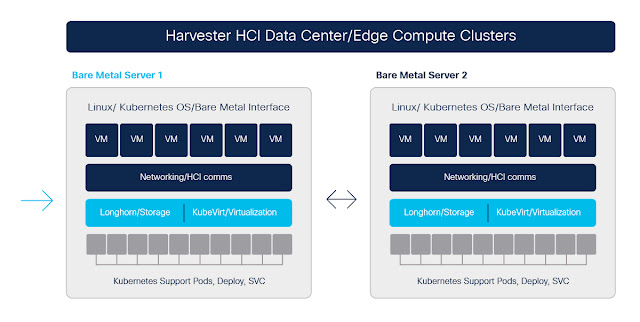
Multi-node Harvester cluster

However, most of the current products that support converged infrastructure tend to lock customers to using their company’s own technology, and they also usually come with licensing fees. Now, there is nothing wrong with paying for a technology when it helps you solve your problem. But single-vendor solutions can wall you off from knowing exactly how these technologies work, limiting your flexibility to innovate or react to issues.

If you could use a technology that combines with other technologies you are already required to know today – like Kubernetes, Linux, containers, and cloud native – then you could theoretically eliminate some of the headaches of managing edge compute / data centers, while also lowering costs.

This is what the people building Harvester are attempting to do.

Adapting to the speed of change


Cloud providers have made it easier to deploy and manage the infrastructure surrounding applications. But this has come at the expense of control, and in some cases performance.

HCI, which the cloud providers support and provide, gets us some control back. However, the recent rise of application containers, over virtual machines, changed again how infrastructure is managed and even thought of, by abstracting layers of application packaging, all while making that packaging lighter weight than last-generation VM application packaging. Containers also provide application environments that are  faster to start up, and easier to distribute because of the decreased image sizes. Kubernetes takes container technologies like Docker to the next level by adding in networking, storage, and resource management between containers, in an environment that connects everything together. Kubernetes allows us to integrate microservice applications with automation and speedy deployments.

Kubernetes offers an improvement on HCI technologies and methodologies. It provides a better way for developers to create cloud agnostic applications, and to spin up workloads in containers more quickly than traditional VM applications. Kubernetes did not aim to replace HCI, but it did make a lot of the goals of software deployment and delivery simpler, from an HCI perspective.

In a lot of environments, Kubernetes runs inside VMs. So you still need external HCI technology to manage the underlying infrastructure for the VMs that are running Kubernetes. The problem now is that if you want to run your application in Kubernetes containers on infrastructure you have control of, you have different layers of HCI to support.  Even if you get better application management with Kubernetes, infrastructure management becomes more complex. You could try to use vanilla Kubernetes for every part of your edge-compute / data center stack and run it as your bare metal operating system instead of traditional HCI technologies, but you have to be ok migrating all workloads to containers, and in some cases that is a high hurdle to clear, not to mention the HCI networking that you will need to migrate over to Kubernetes.

The good news is that there are IoT and Edge Compute projects that can help. The Rancher organization, for example is creating a lightweight version of Kubernetes, k3s, for IoT compute resources like the Raspberry Pi and Intel NUC computers. It helps us push Kubernetes onto more bare metal infrastructure. Other orgs, like KubeVirt, have created technologies to run virtual machines inside containers and on top of Kubernetes, which has helped with the speed of deployment for VMs, which then allow us to use Kubernetes for our virtual networking layers and all application workloads (container and VMs). And other technology projects, like Rook and Longhorn, help with persistent storage for HCI through Kubernetes.

If only these could combine into one neat package, we would be in good shape.

Hyperconverged everything


Knowing where we have come from in the world of Hyperconverged Infrastructure for our Data Centers and our applications, we can now move on to what combines all these technologies together. Harvester packages up k3s (light weight Kubernetes), KubeVirt (VMs in containers), and Longhorn (persistent storage) to provide Hyperconverged Infrastructure for bare metal compute using cloud native technologies, and wraps an API / Web GUI bow on it to for convenience and automation.

Source: cisco.com

Saturday 26 March 2022

Why Transition to BGP EVPN VXLAN in Enterprise Campus

Network Virtualization Convergence in Enterprise Campus

Campus networks are the backbone of enterprises providing connectivity to critical services and applications. Throughout time many of these networks were deployed with a variety of overlay technologies including technologies to accomplish the desired outcome. While these traditional overlay technologies accomplished the technical and business requirements, many of them lacked manageability and scalability introducing complexity into the network. The industry-standard BGP EVPN VXLAN is a converged overlay solution providing unified control-plane-based layer-2 extension and layer-3 segmentation over IP underlay. The purpose-built technology for Enterprise campus and datacenter addresses the well-known classic networking protocols challenges while providing L2/L3 network services with greater flexibility, mobility, and scalability.

Cisco Exam Prep, Cisco Tutorial and Materials, Cisco Career, Cisco Skills, Cisco Jobs, Cisco Certification
Fig #1: BGP EVPN VXLAN converges Layer 2 and Layer 3

Legacy Layer 2 Overlay Networks Departure


Enterprise campus networks have historically been deployed with several types of Layer 2 overlay network extensions as products and technologies evolved. Classic data-plane based Layer 2 extended networks built upon a flood-n-learn basis can be significantly simplified, scaled, and optimized when migrating away to next-generation BGP EVPN VXLAN solution:

◉ STP – Enterprise campus networks have operated spanning-tree protocol (STP) since its inception. Several enhancements and alternatives have been developed to simplify and optimize STP complexity, however, it continued to be challenging. The BGP EVPN VXLAN replaces STP with an L2 overlay enabling new possibilities to IT including controlling flood-domain size, suppressing redundant ARP/ND network traffic, and seamless mobility while retaining the original IPv4/v6 address plan when transitioning from Distribution switch or centralized firewall gateway running over STP network.

◉ 802.1ad – The IEEE 802.3ad (QinQ) is a common multi-tenant Layer 2 network solution. The dual-stack IEEE 802.1Q header tunnels individual tenant VLANs over limited and managed core VLANs to assist in reducing the bridging domain and overlapping tenant VLAN IDs across the core network. BGP EVPN VXLAN enables the opportunity to transform the Layer 2 backbone network with a simplified IP transport utilizing VXLAN and continue to bridge single or dual-stack IEEE 802.1Q VLAN across the fabric. 

◉ L2TPv3 – Layer 2 Protocol Tunnel version 3 (L2TPv3) provides simple point-to-point L2 overlay extension solution over an IP core between statically paired remote network devices. Such flood-n-learn based Layer 2 overlay networks can be migrated to BGP EVPN VXLAN providing far advanced and flexible Layer 2 extension solutions across an IP core network. 

◉ VPWS/VPLS – The standards ratified several Layer 2 network extensions as the industry evolved towards high-speed Metro-Ethernet networking across MAN/WAN. The Enterprise networks quickly evolve adopting Ethernet over MPLS (EoMPLS) or Virtual Private LAN Service (VPLS) solution operating over IP/MPLS based backbone. The Enterprise network can be simplified, optimized, and resilient with BGP EVPN VXLAN supporting flexible Layer 2 overlay topologies with control-plane based Layer 2 extensions that assist in improving end-to-end network performance and user experience. 

Traditional Layer 3 Overlays Convergence


Like Layer 2 extended networks, segmented Layer 3 networks can be deployed with various overlay technologies. The parallel running protocol set with each supporting either routing or bridging may add complexity as network growth and demands expand linearly. As BGP EVPN VXLAN converges routing and bridging capabilities it assists in reducing control-plane and operational tasks resulting in simplicity, scale, and resiliency.

◉ Multi-VRF – A simple hop-by-hop Layer 3 virtual network segmenting Layer 3 physical interface into logical IEEE 802.Q VLAN for each virtual network small to mid-size network environments. As segmentation requirements increase, IT operational challenges and control-plane overhead to manage Multi-VRF also increase. The BGP EVPN leverages IP VRF to dynamically build a segmented routed network environment and with VXLAN the data-plane segmentation is managed at the network edge enabling simplified underlay IP core and scalable Layer 3 overlay routed network solution. 

◉ GRE – An ideal solution for building overlay networks across IP networks without implementing hop-by-hop in the underlay network. The GRE-based overlay solution supports limited point-to-point or point-to-multipoint topologies.  Following similar principles, the BGP EVPN VXLAN can simplify the network with a single control plane, dynamically build VXLAN tunnels, and supports flexible overlay routing topologies. The ECMP based underlay and overlay networks support best-in-class resiliency for mission-critical networks.  

◉ MPLS VPN – The MP-BGP capabilities have been widely adopted in large Enterprises addressing network segmentation across self-managed IP/MPLS managed networks. The well-proven and scalable MPLS VPN in Enterprise overcomes several alternative technologies challenges using shim-layer label switching solution. The MPLS VPN enabled Enterprise networks can extend existing MP-BGP designs and transition VPNv4/VPNv6 to new L2VPN EVPN address-family supporting seamless migration. The edge-to-edge VXLAN data-plane can converge MPLS VPNs, mVPN, and VPLS overlay into a single unified control plane and enable enhanced integrated routing and bridging function. It further assists in greatly simplifying IP core network without MPLS LDP protocol dependencies across the paths. 

Cisco Catalyst 9000 – Seamless and Flexible BGP EVPN VXLAN Transition


Transitioning from classic products and technologies has never been an easier task, especially when mission-critical downtime is practically impossible. The Cisco Catalyst 9000 combined with 30+ years of software innovation with the industry’s most sophisticated network operating system Cisco IOS-XE® provides great levels of flexibility to seamlessly adapt BGP EVPN VXLAN for Enterprise customers as part of an existing operation or planning to begin a new networking journey while maintaining full-backward compatibility with classic products and overlays networks supporting non-stop business communications. 

Cisco Exam Prep, Cisco Tutorial and Materials, Cisco Career, Cisco Skills, Cisco Jobs, Cisco Certification
Fig #2: BGP EVPN VXLAN design alternatives

The end-to-end network and rich feature integration can be enabled independent of how underlying network infrastructure is built as illustrated above.

  Layer 3 Access Cisco StackWise Virtual  ESI Layer 2 Multihome 
Leaf Layer  Access  Distribution  Distribution 
Spine Layer   Core or other     
Border Layer   Data Center ACI, WAN, DMZ or more     
Overlay Network Type Support   Layer 3 Routed, Distributed AnyCast Gateway (Symmetric IRB), Centralized Gateway (Asymmetric IRB)
Layer 2 Cross-Connect 
   
Overlay Unicast Support   IPv4 and IPv6 Unicast     
Overlay Multicast Support   IPv4 and IPv6 – Tenant Routed Multicast     
Wireless Network Integration   Local Mode – Central Switching
FlexConnect Mode – Central and Distributed Local Switching 
   
Data Center Integration   BGP EVPN VXLAN – Common EN/DC Fabric
Cisco ACI – Nexus 9000 Border Layer 3 Handoff 
   
Multi-site EVPN Domain   Campus Catalyst 9000 switches extending fabric with Nexus 9000 Multi-site Border Gateway integration     
External Domain Handoff   L2: Untag, 802.1Q, 802.1ad, EoMPLS, VPLS
L3: Multi-VRF, MPLS VPN, SD-WAN, GRE 
   
Data Plane load sharing   L3: ECMP  L2: Per flow Port-Channel Hash
L3: ECMP
Multicast:S, G + Next Hop
L2: Per Port-VLAN Load Balancing
L3: EMCP
Multicast: S, G + Next Hop
System Resiliency Cisco StackWise-1T
Cisco StackWise-480
Cisco StackPower
Fast Reload
Stateful Switchover (SSO)
Ext. Fast Software Upgrade
In-Service Software Upgrade (ISSU)
Cisco StackWise Virtual
Stateful Switchover (SSO)
In-Service Software Upgrade (ISSU)
Stateful Switchover (SSO)
In-Service Software Upgrade (ISSU)
Network Resiliency BFD (Single/Multi-Hop)
Graceful Restart
Graceful Insertion
L2: EtherChannel, UDLD, etc.
BFD (Single/Multi-Hop)
Graceful Restart
Graceful Insertion
L2: UDLD, etc.
BFD (Single/Multi-Hop)
Graceful Restart
Graceful Insertion

Scalable Architecture Matters


IT organizations adopting the BGP EVPN VXLAN solution must consider how to scale multi-dimensionally when building large-scale fabrics. This demands call-to-action to design the right architecture based on proven principles in the networking world. Regardless of physical or virtual networking, it shall be designed with an appropriate level of hierarchy to support the best-in-class scalable solution supporting a large enterprise network. The smaller fault domains and condensed network topologies in core-layer enable resilient networks are well-known benefits of hierarchical networking.

As the number of EVPN leaf nodes increases overlay prefixes and the blast radius in the network grows. The network architects shall consider building a structured Multi-Site overlay networking solution allowing Enterprise campus to grow by dividing fabric domains in different boundaries and using fabric border gateways to interconnect all together.

Stay tuned we’ll share more thoughts on how Cisco Catalyst 9000 and Nexus 9000 can bring next-generation BGP EVPN VXLAN with Multi-site solutions. And as always, if you are already on the journey to design and build a scalable end-to-end BGP EVPN VXLAN campus network, then simply reach out to your Cisco sales team to partner with you and enable the vision. 

Source: cisco.com

Thursday 24 March 2022

Why Automation Will Unlock The Power of AI in Networking (Part 1)

Cisco Certification, Cisco Learning, Cisco Guides, Cisco Preparation, Cisco Skills, Cisco Jobs, Cisco Materials

You have probably heard about the old adage “Correlation does not imply causation”. This idea that one cannot deduce a causal relationship between two events merely because they occur in association has a cool latin name: cum hoc ergo propter hoc (“with this, therefore because of this”), which hints at the fact that this adage is even older than you might think.

What most people don’t know is that all the cool deep learning algorithms out there actually fall prey to this fallacy. No matter how fancy they are, these algorithms merely rely on association, but they have no common sense (which can be thought of as some kind of causal model of the world).

In this article, we will explore a few key ideas around the topics of correlation and causality, and more importantly, why you should care about this and how automation can help us in this regard!

Correlation by chance

If you have an interest in data analytics or statistics, you have probably come across the concept of spurious correlations. This term has been coined by the famous statistician Karl Pearson in the late 19th century, but has been recently popularized by the Spurious Correlations website (and book) by Tyler Vigen, which offers many examples such as this one:

Here we observe that the number of non-commercial space launches in the world happens to match almost perfectly the number of sociology doctorates awarded in the US every year (in terms of relative variation, not in absolute value). These examples are of course meant as jokes, and this makes us laugh because it goes against common sense. There isn’t any connection between space launches and sociology doctorates, so it is pretty clear that something is wrong here.

Cisco Certification, Cisco Learning, Cisco Guides, Cisco Preparation, Cisco Skills, Cisco Jobs, Cisco Materials

Now, examples such as this one are not exactly what Karl Pearson had in mind when he coined the term, because they are the result of chance rather than a common cause. Instead, we are dealing with a problem of statistical significance: although the correlation coefficient is nearly 79%, this is based only on 13 data points for each series, which makes the possibility of correlation by chance very real. Actually, statisticians have designed tools to compute the probability that two completely independent processes (such as space launches and sociology doctorates) produce data that have a correlation at least as extreme as a given value: statistical testing (in which case this probability is called a p-value). 

I applied a statistical test for the above example (see this notebook if you want to test it yourself and see other examples), and I obtained a p-value of 0.13%. I also tested this result empirically by generating one million random time-series and counting how many such time-series had a correlation with the number of worldwide non-commercial space launches higher than 78.9%. No surprises here, I get roughly 0.13% of my trials falling in that category. This summarized in this figure:

Cisco Certification, Cisco Learning, Cisco Guides, Cisco Preparation, Cisco Skills, Cisco Jobs, Cisco Materials

One important lesson here is: by searching long enough in a large dataset, you will always find some examples of nicely correlated examples. By no means you should conclude that there is some actual relation between them, let alone some causation!

Correlation due to common causes


Now, you can be in a situation where not only the correlation is high, but the sample count is also high, and statistical testing will be of no help (that is, in the above example, you would never be able to generate a random time-series more correlated than your real data). Yet, you cannot conclude that you are in presence of a real situation of causation!

To illustrate this fact vividly, consider the following (made up) example featuring two processes: process A generates a time-series and process B generates discrete events. A realization of these processes is shown below:

Cisco Certification, Cisco Learning, Cisco Guides, Cisco Preparation, Cisco Skills, Cisco Jobs, Cisco Materials

We observe a systematic build up of time-series A, followed by an event B. For the sake of the illustration, let us assume that we have a very large dataset of such time-series and event data, and they all look pretty much like my diagram. The above example has a correlation of 27.62% and an infinitesimal p-value, which rules out correlation by chance. The build up of A happens prior to the event B, so it seems clear that it is a cause of B, right?

But what if I told you that A represents the number of people observed on a platform in a train station and that B corresponds to the arrival of a train on this platform? Then it all makes sense of course. Passengers accumulate on the platform, the train arrives, and most passengers hop on the train. Does that mean that the passengers cause the train to arrive? Of course not! These processes do not cause each other, but they share a common cause: the timetable!

Source: cisco.com

Tuesday 22 March 2022

Get Ready for Machine Learning Ops (MLOps)

There are a lot of articles and books about machine learning. Most focus on building and training machine learning models. But there’s another interesting and vitally important component to machine learning: the operations side.

Let’s look into the practice of machine learning ops, or MLOps. Getting a handle on AI/ML adoption now is a key part of preparing for the inevitable growth of machine learning in business apps in the future.

Machine Learning is here now and here to stay

Under the hood of machine learning are well-established concepts and algorithms. Machine learning (ML), artificial intelligence (AI), and deep learning (DL) have already had a huge impact on industries, companies, and how we humans interact with machines. A McKinsey study, The State of AI in 2021, outlines that 56% of all respondents (companies from various regions and industries) report AI adoption in at least one function. The top use-cases are service-operations optimization, AI-based enhancements of products, contact-center automation and product-feature optimization. If your work touches those areas, you’re probably already working with ML. If not, you likely will be soon.

Several Cisco products also use AI and ML. Cisco AI Network Analytics within Cisco DNA Center uses ML technologies to detect critical networking issues, anomalies, and trends for faster troubleshooting. Cisco Webex products have ML-based features like real-time translation and background noise reduction. The cybersecurity analytics software Cisco Secure Network Analytics (Stealthwatch) can detect and respond to advanced threats using a combination of behavioral modeling, multilayered machine learning and global threat intelligence.

The need for MLOps

When you introduce ML-based functions into your applications – whether you build it yourself or bring it in via a product that uses it —  you are opening the door to several new infrastructure components, and you need to be intentional about building your AI or ML infrastructure. You may need domain-specific software, new libraries and databases, maybe new hardware such as GPUs (graphical processing units), etc. Few ML-based functions are small projects, and the first ML projects in a company usually need new infrastructure behind them.

This has been discussed and visualized  in the popular NeurIPS paper, Hidden Technical Debt in Machine Learning Systems, by David Sculley and others in 2015. The paper emphasizes that it’s important to be aware of the ML system as a whole, and not to get tunnel vision and only focus on the actual ML code. Inconsistent data pipelines, unorganized model management, a lack of model performance measurement history, and long testing times for trying newly introduced algorithms can lead to higher costs and delays when creating ML-based applications.

The McKinsey study recommends establishing key practices across the whole ML life cycle to increase productivity, speed, reliability, and to reduce risk. This is exactly where MLOps comes in.

Cisco Prep, Cisco Certification, Cisco Career, Cisco Skills, Cisco Jobs, Cisco MLOps, Cisco Machine Learning
Looking at a ML architecture holistically, the ML code is only a small part of the whole system.

Understanding MLOps


Just as the DevOps approach tries to combine software development and IT operations, machine learning operations (MLOps) –  tries to combine data and machine learning engineering with IT or infrastructure operations.

MLOps can be seen as a set of practices which add efficiency and predictability to the design, build phase, deployment, and maintenance of machine learning models. With a defined framework, we can also automate machine learning workflows.

Here’s how to visualize MLOps: After setting the business goals, desired functionality, and requirements, a general machine learning architecture or pipeline can look like this:

Cisco Prep, Cisco Certification, Cisco Career, Cisco Skills, Cisco Jobs, Cisco MLOps, Cisco Machine Learning
A general end-to-end machine learning pipeline.

Infrastructure

The whole machine learning life cycle needs a scalable, efficient and secure infrastructure where separate software components for machine learning can work together. The most important part here is to provide a stable base for CI/CD pipelines of machine learning workflows including its complete toolset which currently is highly heterogenous as you will see further below.

In general, proper configuration management for each component, as well as containerization and orchestration, are key elements for running stable and scalable operations. When dealing with sensitive data, access control mechanisms are highly important to deny access for unauthorized users. You should include logging and monitoring systems where important telemetry data from each component can be stored centrally. And you need to plan where to deploy your components: Cloud-only, hybrid or on-prem. This will also help you determine if you want to invest in buying your own GPUs or move the ML model training into the cloud.

Examples of ML infrastructure components are:

◉ Kubernetes
◉ Public cloud providers
◉ On-premise hardware like Cisco Hyperflex and Unified Computing System.
◉ OpenStack

Data sourcing

Leveraging a stable infrastructure, the ML development process starts with the most important components: data. The data engineer usually needs to collect and extract lots of raw data from multiple data sources and insert it into a destination or data lake (for example, a database). These steps are the data pipeline. The exact process depends on the used components: data sources need to have standardized interfaces to extract the data and stream it or insert it in batches into a data lake. The data can also be processed in motion with streaming computation engines.

Data sourcing examples include:

◉ Stream processing: Apache Kafka, fluentd
◉ Streaming Computation Engine: Apache Spark , Apache Flink
◉ Any databases (relational, non-relational): PostgreSQL, MongoDB, influxDB
◉ Data lake platforms and data warehouses

Data management

If not already pre-processed, this data needs to be cleaned, validated, segmented, and further analyzed before going into feature engineering, where the properties from the raw data are extracted. This is key for the quality of the predicted output and for model performance, and the features have to be aligned with the selected machine learning algorithms. These are critical tasks and rarely quick or easy. Based on a survey from the data science platform Anaconda, data scientists spend around 45% of their time on data management tasks. They spend just around 22% of their time on model building, training, and evaluation.

Data processing should be automated as much as possible. There should be sufficient centralized tools available for data versioning, data labeling and feature engineering.

Data management examples:

◉ Data version control: Pachyderm
◉ Feature storage: Feast
◉ Data Exploration: Pandas
◉ Data labeling (for images): CVAT

ML model development

The next step is to build, train, and evaluate the model, before pushing it out to production. It is crucial to automate and standardize this step, too. The best case would be a proper model management system or registry which features the model version, performance, and other parameters. It is very important to keep track of the metadata of each trained and tested ML model so that ML engineers can test and evaluate ML code more quickly.

It’s also important to have a systematic approach, as data will change over time. The previously selected data features may have to be adapted during this process in order to be aligned with the ML model. As a result, the data features and ML models need to be updated and this again will trigger a restart of the process. Therefore, the overall goal is to get feedback of the impact of their code changes without many manual process steps.

ML model development examples:

◉ ML frameworks: Tensorflow, PyTorch, Keras
◉ Notebook / code management: Jupyter
◉ Model management: Kubeflow
◉ Experiment tracking: mlflow, Tensorboard

Production

The last step in the cycle is the deployment of the trained ML model, where the inference happens. This process will provide the desired output of the problem which was stated in the business goals defined at project start.

How to deploy and use the ML model in production depends on the actual implementation. A popular method is to create a web service around it. In this step it is very important to automate the process with a proper CD pipeline. Furthermore, it’s crucial to keep track of the model’s performance in production, and its resource usage. Load balancing also needs to be engineered for the production installation of the application.

ML production examples:

◉ Model serving: BentoML, KServe, Seldon core
◉ Model observability: Evidently
◉ Logging & monitoring: Grafana, Prometheus

Where to go from here?


Ideally, the project will use a combined toolset or framework across the whole machine learning life cycle. What this framework looks like depends on business requirements, application size, and the maturity of ML-based projects used by the application.

Source: cisco.com

Sunday 20 March 2022

Private 5G Delivered on Your Terms

SP360: Service Provider, Featured, IOT, 5G, Service Provider, Cisco Exam Prep, Cisco Career, Cisco Skills, Cisco Jobs, Cisco 5G

Private 5G is a hot topic as enterprises seek industrial wireless IoT solutions to modernize their business for increased productivity and efficiency. In newly emerging cases, wired solutions are not enough, such as in sectors like hospitality where “protected buildings” limit running new cables. For manufacturing and other industries, critical processes like robotic assembly of essential parts (jet turbines, automotive transmissions, or medical devices) and autonomously guided vehicles need a very low-latency, high-reliability solution like private 5G, particularly when those processes co-exist with humans.

On Feb. 3, 2022, we introduced Cisco Private 5G as part of “The Network. Powering Hybrid Work” launch. During this event, we shared our view that the future of hybrid work expands beyond people collaborating with people and now includes people collaborating with things. We now begin to share many attractive use cases for introducing private 5G alongside Wi-Fi into the enterprise networks. As we move towards Mobile World Congress (MWC) at the end of February, we’ll reveal more about our private 5G go-to-market strategies and discuss exciting new opportunities for our global service provider partners.

Connecting everyone and everything


Wireless networking and IoT will transform industries by digitalizing Operational Technology (OT) just as profoundly as the cloud transformed Information Technology (IT). And enterprises are already waiting in anticipation, with a 2021 GSMA Intelligence market report showing that a combination of digital transformation and labor shortages is expected to see enterprise IoT connections quadruple to 23.6 billion by 2030, accounting for 63 percent of total IoT connections. With all the pieces in place, companies with a strategy to converge their IT and OT operations will experience significant gains in productivity and efficiency, creating a major competitive advantage.

With the convergence of IT and OT, hybrid work becomes about connecting everyone and everything. Delivering IoT at scale is just as important as connecting people, allowing hybrid workers to gain access to sensors, monitors, robots, and more. Our vision of the future of work is built on wireless through a combination of private 5G and Wi-Fi, where enterprises can modernize, automate their operations, and benefit from the resulting productivity gains.

But making the change is not easy. There are all kinds of confusing options right now, so where do you begin? We can help by delivering a private 5G solution on your terms.

What separates Cisco Private 5G from the rest?


We believe the competitors are going about it the wrong way. They would have you adopt a complex, carrier-centric 5G solution that’s radically different from what you already know and use. Some even ignore Wi-Fi entirely. As the top enterprise networking, wireless, security, Industrial IoT, and collaboration IT vendor, we know how to build a solution that fits your enterprise needs, where Cisco Private 5G is integrated with Wi-Fi and existing IT operations environments. This makes your transformation easy, and we’re the only vendor to empower enterprise customers to extend what they already own and understand into new possibilities.

SP360: Service Provider, Featured, IOT, 5G, Service Provider, Cisco Exam Prep, Cisco Career, Cisco Skills, Cisco Jobs, Cisco 5G

We know the many different technology choices and complexity of operating such an environment can make it difficult to start. It’s hard to commit financially to a new technology with so many uncertainties. Even the most visionary business leaders may hesitate to avoid making a wrong decision. With Cisco as your partner, you can feel confident you’ve made the right choice because our private 5G solution is ‘Simple to Start’, ‘Intuitive to Operate’, and ‘Trusted’ for enterprise digital transformation.

Simple to start

◉ The journey begins with a qualified business consultation.

◉ You don’t have to choose between 5G and Wi-Fi – you can use both, protecting your current investments and strategies.

◉ With your business goals in hand, a premium partner will perform a site survey to scope the necessary networking and radio coverage to support the intended IoT use case(s).

◉ Cisco Private 5G networks will be Cisco Validated Designs (CVD).

◉ Our “pay-as-you-use” subscription model means that you and your deployment partners will have minimal up-front infrastructure costs, so no matter how small the start or how massive the goal, costs remain in line with value. By comparison, traditional purchasing models force you to “spend a lot and wait” for productivity or profitability.

Intuitive to operate

◉ A simple management portal integrates and aligns with existing enterprise tools. We handle all the complexities of the 3GPP mobile network stack.

◉ Enterprise IT teams get a complete picture of their network and devices. You can maintain policy and identity across wired and wireless network domains for simplified operations.

◉ AI/ML-based management tools can identify unexpected behavior patterns and potential issues, making it easy to proactively take intelligent actions. Intelligent analytics increase effectiveness, minimize exposure time and reduce damage.

◉ Many problems in the network stem from outdated software, and nearly all are avoidable. As a continuously improving service, our private 5G software releases are automatically maintained from the cloud, ensuring the latest functions and security updates are in place.

Trusted

◉ As the No. 1 provider for connectivity, collaboration, industrial IoT, and IoT-connected cars, enterprises trust our technology, products, and services.

◉ Cloud-native architecture allows Cisco Private 5G to flexibly support different deployment models. Components may reside in the cloud, distributed edge, or on premises depending on needs for extra reliability or data privacy.

Source: cisco.com

Saturday 19 March 2022

Cisco Radio Aware Routing

Cisco Radio Aware Routing addresses several of the challenges faced when merging IP routing and radio communications in mobile networks, especially those exhibiting ad hoc (MANET) behavior. This technology has applications in the defense industry as well as state and local government for search and rescue, law enforcement, and disaster assessment.

Looking at the Real-World Problem Description – Mesh Topology


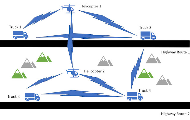
The above network is a voice, video, and data network between moving vehicles that consists of both ground and air vehicles. This mobile network is a peer-to-peer mesh that changes as topographical obstructions are encountered and is called “mobile ad hoc network” or MANET for short.


In the scenario shown above, all 4 trucks have a reliable, consistent connection with the helicopters flying over the same road. The two helicopters always have line of sight and will always have a connection between each other. The trucks may even be able to connect to the other helicopter or a truck on the opposite road when conditions are favorable. Here we see that the path between trucks 1 and 3 are completely blocked. The path between Truck 2 and 4 is about to be blocked.

Our existing routing protocols such as OSPFv3 and EIGRP need to adjust their path metrics very quickly to maintain a cohesive operational network. The routing protocol also needs a way to get information from the radios, requiring a radio to router protocol that is delivered by Cisco Radio Aware Routing in the form of two open protocols, which we will discuss here.

Cisco Radio Aware Routing provides capabilities that facilitate:

◉ Optimal route selection based on cross-layer feedback from cooperating radios

◉ Faster convergence when nodes join and leave the network

◉ Flow-controlled communications between the radio and its partner router

◉ Efficient integration of point-to-point, directional radio topologies with multihop routing

◉ Neighbor Up / Down Status

Here is a schematic view of a piece of the network:


What Are Underlying Technical Problems that Need to be Solved?


◉ Fluctuations in radio link quality affect throughput and need to be factored into route cost calculation.

◉ The self-forming, self-healing nature of a mobile ad hoc network requires immediate recognition of topology changes to help ensure fast convergence.

◉ Radios need to control the rate at which routers send information to minimize the need for queuing within the radio.

◉ Directional radios form point-to-point or point-to-multipoint networks with neighbors, which increases the size of the router’s database and reduces routing efficiency.

What Are the Benefits of Radio Aware Routing?


◉ Enables network-based applications and information to be delivered reliably and quickly over directional radio links.

◉ Provides faster convergence and optimal route selection so that delay-sensitive traffic, such as voice and video, is not disrupted.

◉ Reduces impact on radio equipment by minimizing the need for internal queuing/buffering; also provides consistent quality of service for networks with multiple radios. 

How Radio Aware Routing Works – Currently Two MANET Choices


Today, radios have 2 possible RAR protocols which are both supported in select Cisco routers:

1. RFC-5578 – PPP over Ethernet (PPPoE) Extensions for Credit Flow and Link Metrics

2. RFC-8175 – Dynamic Link Exchange Protocol (DLEP)

The actual choice of protocols is largely dependent on the radio vendor and the intended applications and optimization of their devices.

RFC 5578 and RFC 8175 provide an effective, cross-layer mechanism for communicating radio network status to IP routers – RFC 5578 primarily for Time Division Multiple Access (TDMA) style radios and RFC 8175 is primarily for multiaccess shared media radios that is very similar to WiFi. 

(1) RFC 5578 – PPP over Ethernet (PPPoE) Extensions for Credit Flow and Link Metrics

This solution, based on Internet Engineering Task Force (IETF) Request for Comments (RFC) 5578, employs PPP over Ethernet (PPPoE) sessions to facilitate intranodal communications between a router and a compliant device, such as a mobile radio or satellite modem. A PPPoE session is established between router and radio on behalf of every other router/radio neighbor. Once these PPPoE sessions are established, a PPP session is established end to end. This protocol is particularly suited for TDMA style radios.

Cisco Radio Aware Routing (RAR) using RFC 5578 is specifically targeted at routing over directional radio networks that are built with point-to-point links.

From the abstract of the RFC Document:

“This document extends the Point-to-Point Protocol over Ethernet (PPPoE) with an optional credit-based flow control mechanism and an optional Link Quality Metric report. These optional extensions improve the performance of PPPoE over media with variable bandwidth and limited buffering, such as mobile point-to-point radio links.”


◉ Neighbor Up/Down Signaling: Enables Cisco routers to provide faster network convergence by reacting to link status signals generated by the radio, rather than waiting for protocol timers to expire. The routing protocols (OSPFv3 or EIGRP) respond immediately to these link status signals by expediting adjacency formation or tear-down.

◉ Link Quality Metrics Reporting: The PPPoE protocol has been extended to enable a radio to report link quality metric information to a router. Cisco routers have been enhanced so that OSPFv3 or EIGRP routing protocols can factor link quality metrics into route cost calculations.

◉ PPPoE Credit-Based Flow Control: This PPPoE extension allows a receiver to control the rate at which a sender can transmit data for each PPPoE session, so that the need for queuing in the radio is minimized.


(2) RFC 8175 – Dynamic Link Exchange Protocol (DLEP)

DLEP is a control protocol between a router and a DLEP enabled radio MODEM. The DLEP message exchange between the router and radio allow the radio to tell the router about the link quality. This is somewhat analogous to the way the bar icon on your cell phone tells you about your WiFi or LTE signal quality.


From the abstract of the RFC Document:

“When routing devices rely on modems to effect communications over wireless links, they need timely and accurate knowledge of the characteristics of the link (speed, state, etc.) in order to make routing decisions. In mobile or other environments where these characteristics change frequently, manual configurations or the inference of state through routing or transport protocols does not allow the router to make the best decisions.  This document introduces a new protocol called the Dynamic Link Exchange Protocol (DLEP), which provides a bidirectional, event-driven communication channel between the router and the modem to facilitate communication of changing link characteristics.”

DLEP is better suited for multi-access shared media radios that are very similar to WiFi.

How Does DLEP Help?

◉ Without DLEP these are 2 equal cost paths to any unadjusted routing protocol.
◉ With DLEP routing metrics can be adjusted in real-time to favor the best path.
◉ With DLEP the radio network conditions reported can also be used in the router’s Quality of Service (QoS) traffic shaping decisions.
◉ With DLEP we have Neighbor Up/Down Status.


Atmospheric conditions and interference will ultimately favor one band vs. the other. While this example was simplified by only considering a point-to-point technology, DLEP is actually optimized for radio mesh topologies.

Why Cisco?


Cisco Radio Aware Routing is the industry’s first router-based implementation of RFC 5578 and RFC 8175. As the global leader in mission-critical networking and IP communications, Cisco is uniquely positioned to deliver reliable and efficient converged voice, video, and data solutions to organizations around the world. Cisco solutions are backed by award-winning technical support and advanced services.

Source: cisco.com

Thursday 17 March 2022

Unified Software Tracing Comes to Cisco IOS XE – It’s Unified, Binary, Streaming, and Highly Scalable

Software tracing is essential for Cisco’s team of enterprise networking software engineers, along with the legions of developers, systems admins, and tech support personnel among our customers. Tracing is the specialized use of logging to capture the operational behavior of code down to the code execution path. It’s indispensable for developers for troubleshooting network software in production to catch bugs, errors, misconfigurations, or other problems throughout the birth and lifecycle of products.

Cisco has provided a more efficient and effective way to use network software traces at scale for our 80+ enterprise platforms. It’s called unified tracing.

With unified tracing, all traces deployed in software running anywhere in the system (e.g., in line cards or other field replaceable units [FRUs]), are streamed to the main processor of the Cisco device and collected in a single set of files. This integration of trace messages provides time-ordered, real-time visibility into what a router, switch, wireless controller, or Internet of Things (IoT) device is doing across its approximately 100 processes.

Here’s how we’ve ramped up tracing in a big way and what it means for enterprise networking.

Tracing Gets Binary in Cisco IOS XE 16.0

Release 16.x introduced binary tracing to the Cisco IOS XE code base. It’s now widely used.

Binary tracing relies on compiler technology to assist in the encoding of each trace point, allowing for the storage of non-ASCII text objects, like packets and software-generated objects in the trace stream. These binary objects provide richer operational information about how network platforms are performing.

Fully distributed, binary tracing also enables tracing on steroids, with some Cisco enterprise platforms able to exceed peak trace rates of two million traces per second per process. It also separates the encoding of high-performance traces from the decoding of traces, which can be displayed to users later.

Unified Tracing introduced in Cisco IOS XE Release 17.7

With binary tracing alone, each process writes traces independently to separate files. If you have 100 processes, you have 100 separate sets of files, which slows down troubleshooting.

With unified tracing, all trace files for a system are merged into one trace file set of messages with all of the information about their origins (Figure 1). Each trace event uniquely identifies the calling site information and carries context to know where in the system and the source code it was produced.

Cisco IOS XE, Cisco Exam Prep, Cisco Tutorial and Materials, Cisco Guides, Cisco Career, Cisco Learning, Cisco Skills, Cisco Jobs
Figure 1. From Per-Process Binary Trace Files (BTF) to Unified Trace Files (UTF) and Messages

Users can filter the time-ordered unified trace messages to make intelligent filtering decisions and see and understand what’s going on in the 100 or so processes at work in each device with greater detail and in real-time. You might notice a large number of errors coming from a single process with unified tracing. Then you can inspect the code and quickly understand what’s going on. Before, reviewing individual trace files one at a time made this process much slower and not scalable.

Developers don’t have to change a single line of code to enjoy the improved logging performance of unified tracing. They can also continue to use the Buginf API as their Cisco IOS XE debug trace command. The goal was to introduce a uniform way to log information throughout a system regardless of the source, avoiding expensive data transformations or duplicate information logged in different ways for different customers.

Features and Benefits of Unified Tracing


◉ Automated traces from 100+ processes are streamed in real-time, in temporal order, across FRUs to a centralized set of unified trace files

◉ Centralized trace inspection based on high-rate filtering in real time is now possible―an industry first

◉ Richer information is collected on bugs, errors, misconfigurations, etc., across all system processes

◉ Identification of software issues during development and for post-release troubleshooting is accelerated

Additionally, in a coming version of unified tracing, trace files can be exported for use by analytical frameworks to provide further trace inspection and improve troubleshooting and insights. It’s a brand-new feature that also will allow for more efficient use of device disc space because of current CPU limits on the number of traces that can be created. It will enable more traces to be created and the ability to retain trace files elsewhere for the life of a system.

More Meaningful, Scalable Traces


With unified tracing in Cisco IOS XE, customers get a lot more information about what’s happening in their Cisco network devices than ever before. Developers can use unified tracing to finetune performance. Systems administrators and tech support agents can use it for more detailed, faster, and more scalable troubleshooting.

At Cisco we’re continually investing in products to improve the troubleshooting and serviceability of our products and unified tracing is a prime example.

Source: cisco.com

Tuesday 15 March 2022

Randomized and Changing MAC (RCM)

What is Randomized & Changing MAC (RCM)

Historically wireless clients associate to the wireless network using the manufacturer assigned mac address that is associated with the wireless network interface card (NIC). This manufacturer-assigned mac address, which is globally unique, is also known as burn-in address (BIA). Use of this burn-in address everywhere raises the question of end-user privacy as the end-user can be tracked with WIFI’s mac address. In this document, this will be referred to as normal mac (address), in contrast to the random mac (address).

To improve end-user privacy, various operating system vendors (Apple iOS 14, Android 10 and Windows 10) are enabling the use of the locally administered mac address (LAA), also referred to as the random mac address for WIFI operation. When wireless endpoint is associated with random mac address, the MAC address of the endpoint changes over time.

The random mac address was limited to probe for known wireless networks. This is now expanded to association to the wireless networks. While this works well for the privacy of the end-user, it brings unique challenges to the Enterprise IT admin, who has been depending so far on the unique endpoint identity as the basis for driving policies. This will also affect different WIFI deployment models e.g., Guest, BYOD (Bring Your Own Device) and location analytics, etc. which rely on the uniqueness of the mac address.

To address and alleviate the issues due to the usage of random MAC addresses in the existing wireless deployments, Cisco provides an RCM solution.

Fig #1: RCM Cisco Solution

Random Mac Identification and Client access


Cisco solution Identifies the random mac usage and provides visibility for easy detection of issues and troubleshooting on WLC and Cisco DNA Center.

Cisco Catalyst 9800 can classify the device on the network using its Universally administered address (BIA) or Locally administered address (RCM) which helps administrators to distinguish between both mac addresses. Random MAC address is identified by a bit which gets set in the OUI portion of a MAC address to signify a locally administered address. The below picture depicts how to identify the locally administered mac address.

Fig #2: Random MAC Identification

In addition, Cisco 9800 wireless controller also provides the ability to control the client joining WIFI Network using RCM address. This is enabled through a configuration option to allow/deny RCM clients. When this configuration is enabled, then any client using the randomized changing MAC RCM (Locally administered MAC address) will not be able to join that wireless network.

MDM (Mobile Device Manager)/ISE BYOD Integrations:


MDM solution provides a unique device identity when the mac address of the device is randomized and changing. When the endpoint connects to the network using randomized MAC address, MDM compliance check and other security controls fail because of unrecognized random MAC addresses as device identifiers. This solution provides a unique identity to the device based on EAP-TLS which is known as DUID (Device Unique ID) solution.

◉ This solution relies on the MDM (Mobile device manager also referred to as Device managers, Unified Endpoint Managers (for example Ms Intune, Mobile Iron) which manage devices in an enterprise infrastructure.

◉ ISE provides the provisioning of the device with the device’s unique ID-based (DUID) certificates.

◉ The device presents this certificate during TLS based authentication ISE authorizes the devices and also reads the unique ID from the certificate.

◉ The device unique ID (DUID) is used for compliance check with MDM servers and also a unique identifier of the device in the endpoint table.

◉ The randomized MAC will not matter as now the device has a DUID using the ID in the cert.

◉ Since ISE has the mapping of the DUID and the random MAC and it can share this information in two ways
     
     ◉ Through pxGrid as part of session information where Cisco DNA Center is the pxGrid subscriber.
     ◉ WLC gets the client info from ISE as part of VSA access-accept, this info is sent to the Cisco DNA Center.

Fig #3: Device Unique ID MDM Flow

The same use case can be implemented through ISE as part of BYOD workflow as ISE can generate DUID during the BYOD process.

DNA Center visibility, Troubleshooting, Usage tracking for RCM


Fig #4: DNA Center RCM Client Dashboard
 
Using Cisco DNA Center, we will be able to track, troubleshoot and see where the random macs are being used in the network. For the devices using random mac addresses, Cisco DNA Center has introduced a new icon in front of the device MAC address to symbolize RCM. Cisco DNA Center users can filter the devices with mac address as an RCM address for the IT admin to track how many clients are RCM clients in the network.

Below Cisco DNA Center screen shows the filtered RCM Clients for visibility, tracking, and troubleshooting.

Users can see the visibility of the client DUID and random MAC and also which another mac address is related on Cisco DNA Center as shown in the below in Cisco DNA Center Client 360 page.

Fig 5: DNAC RCM Client 360 View

Fig 6: DNA Center RCM Client Details

Cisco DNA Center also shows if clients are not associating to the network because Random MAC is configured not to join the network. Below client screen shows that.

Fig 7: DNA Center RCM Client Association Failure View

Future of Random MAC Solution


Cisco will pursue with IETF to have a formal working group for MAC address device identification for Network and Application Services.

Source: cisco.com