Showing posts with label Wireless and Mobility. Show all posts

Thursday, 13 April 2023

Something New: AP Discovery Methods for 6GHz Wi-Fi – Part 2

In Part 1 (Something Old) we looked at basic changes to the physical layer provided by wave 1 of 801.11ax, how these changes can affect performance, and how OFDMA enables the optimal use of the 6GHz spectrum. In this second article, we’ll explore “something new:” the challenges of discovery in 6GHz, new methods used for solving this, and how these new methods open 6GHz for many different use cases.

Is There Anybody Out There?


In previous generations, Wi-Fi clients would scan channels and send unsolicited probe requests to discover access points (APs). Scanning channels can be a timely process as beacons are only broadcast every 102400us so the client must dwell long enough to detect the beacon. At 6GHz this is 102400us x 59 channels (there are 59 20MHz channels in the new 6GHz spectrum) which is over 6 seconds. For the client, this loss in time represents a disruption in communication. Creating intolerable latency in voice and lost opportunity to hundreds of megabytes of data every time the client decides to scan. Furthermore, the previous process would be to send unsolicited probe requests (wildcard requests) to see how APs would respond. Now, remember, this is all a contention-based medium, so these probe requests and responses on every channel for every client create a significant amount of interference and at the very least, inefficient use of the spectrum.


Over the years the IEEE has introduced measures to address these roaming challenges. 802.11k was introduced to provide clients with a list of neighboring APs, 802.11v was introduced to provide a recommended AP candidate, and 802.11r was introduced to reduce the roaming time for 802.1x clients. Not all clients and infrastructure support these measures so while they helped, they did not eliminate the need for clients to send unsolicited probes.

While these IEEE updates are still available for 6GHz, the strategy for AP discovery fundamentally changes. To start with, unsolicited probe requests are no longer allowed (with one limited exception we will discuss shortly).

Three New Methods to Improve AP Discovery


Since we have already established scanning channels at 6GHz is not allowed, there are three new methods introduced in Wi-Fi 6E for finding AP candidates.

The primary method (and the one that clients typically respond to best) is called Reduced Neighbor Report (RNR). Since most, if not all, clients will have legacy band capability, there is an Information Element (IE) embedded in the legacy band beacons that list the 6GHz SSID(s) that are available on the serving AP. The client first scans the 5GHz or 2.4GHz channels and looks for this RNR element. The RNR report contains information about the 6GHz channel, SSID, BSSID, a bit of information on the AP, and the allowed power levels (Power Spectral Density). This effectively makes the 2.4GHz and 5GHz channels a control channel for the 6GHz. Clients can then send a directed probe request to those channels that are learned in the RNR to determine which 6GHz AP to join. It is important to note there can be multiple 6GHz SSIDs included in the RNR and they do not have to match the legacy SSIDs.

The information contained in an RNR is very similar to the information provided in the previously introduced 802.11v action frame. The RNR below is from a 5GHz beacon and is advertising two SSIDs on the 6GHz channel number 5. The legacy 802.11v action report below shows similar information to the RNR but the fundamental difference is twofold:

◉ This is an action frame not part of the beacon like the RNR. It is a request-response type transaction. An RNR is broadcast in the legacy band beacons.

◉ The information in the 802.11v action frame contains information about other APs on the same frequency band. The RNR only lists SSIDs broadcasted from the 6GHz band (different frequency band) as this same AP.

Cisco Exam, Cisco Exam Prep, Cisco Tutorial and Materials, Cisco Certification, Cisco Prep, Cisco Preparation, Cisco Guides, Cisco Learning
Figure 1: RNR on 5GHz beacon

Cisco Exam, Cisco Exam Prep, Cisco Tutorial and Materials, Cisco Certification, Cisco Prep, Cisco Preparation, Cisco Guides, Cisco Learning
Figure 2: 802.11v Action Frame

What if the AP is only broadcasting 6GHz? This is an unlikely condition, but nonetheless a potential one. First, scanning can be reduced by limiting the number of channels to be scanned. This is called Preferred Scanning Channels (PSC). The PSCs are the primary channels (20MHz subchannel) of the 80MHz channels. This works well since 80MHz will often be the preferred bandwidth to operate for reasons previously discussed in part 1 of this blog series. If however, lower bandwidth channels are used without RNR or additional support from the methods below, it would be very easy for a client to miss this channel which should be a consideration when using PSC with narrower band channels.

Cisco Exam, Cisco Exam Prep, Cisco Tutorial and Materials, Cisco Certification, Cisco Prep, Cisco Preparation, Cisco Guides, Cisco Learning
Figure 3: Preferred Scanning Channels (red)

There are two mutually exclusive options to further enhance the AP discovery in which the AP will broadcast messages an additional 4 times between the beacons or about every 20ms (configurable from 5ms to 25ms). The first method is called Fast Initial Link Setup (FILS) and is based on a previous standard of 802.11ai. This is a very lightweight message (somewhere around 100 bytes as compared to a beacon which is 500+ bytes). The second method is called “Broadcast Probe Response” or “Unsolicited Probe Response” (UPR). Like FILS, this advertisement will be broadcast at a higher rate than the beacon. However, the UPR broadcasts everything in the probe response so while it supplies the client with more information, it is a bit heavier in the amount of data transmitted repeatedly.

Teamwork Makes the Discovery Dream Work


So how do these four methods work together? First, if there are legacy band SSIDs transmitted on the AP the expectation is that the RNR will do the work of discovering the 6GHz channel, and no other method is required. In the case where only 6GHz is broadcast from the AP the most likely scenario would be the use of PSC with either FILS or UPR. Notice UPR and FILS are exclusive options, you can only use one or the other. Early testing of client devices has seen some issues with 6GHz standalone APs not being discovered with only PSC and it is needed to have FILS (or UPR) enabled to assist a client in discovering the AP. This may change over time but for the early implementations, deploying 6GHz with only 80MHz channels and PSC enabled is a good option. This allows the primary channel to match the PSC channels. In addition, enabling FILS can provide further assistance for discovery with minimal impact on performance.

Source: cisco.com

Tuesday, 11 April 2023

Wi-Fi 6E, Something Old, Something New, Something Borrowed, Something Blue – Part 1

With the recent release of a number of Wi-Fi 6E-enabled devices at the Consumer Electronics Show (CES), now is a good time to take into account some of the benefits that Wi-Fi 6/6E provides. Wi-Fi 6/6E was not an “incremental” change, it was a major leap forward with the new innovations and most importantly, the addition of the newly allocated 6GHz spectrum (which varies across regions). In this series, we will provide the reader with an in-depth understanding of some of these advanced features in Wi-Fi 6 and how some of these features benefit them. Furthermore, we will discuss some of the new innovations built around the Wi-Fi 6E standard and how IT leaders are just starting to realize the potential for 6GHz wireless.

“Something Old”


While the ability to support multiple simultaneous users has been available prior to Wi-Fi 6E this is one “old” feature that becomes enhanced in Wi-Fi 6E. In part 1 we want to look at some of the changes to the physical layer, what changed, and how this helps your WiFi performance.

Of all the features added to Wi-Fi 6, one, in particular, will have a very significant effect on the new 6GHz band and deserves some in-depth consideration and that is OFDMA. Remember all that old 802.11ax optional capability is now mandatory at 6GHz as there is no requirement for brownfield support. There were other technologies added to the legacy bands in Wi-Fi 6 that really paved the way for substantial improvements in performance. For example, increased modulation rates (up to 1024 QAM, think of this as higher maximum throughput), better spatial isolation (BSSID Coloring/OBSS and multiple timers for IBSS and OBSS, think of this as better performance in an area with lots of clients and APs), Target Wait Time (better battery life for clients), and others.

Digging into OFDM – The Virtual Wires of Wi-Fi

OFDM is the “baseband” signal which is the underlying waveform that is used to generate the RF signal we think of as Wi-Fi from the digital input. This baseband signal is comprised of multiple “tones”. The combination of these tones is called Orthogonal Frequency Division Multiplexing (OFDM). Each tone is orthogonal to the other tones which means the information on that tone can be detected with limited interference from other tones even though they are tightly spaced together. Think of each of these tones as a wire that information can be conducted. Fewer tones mean fewer wires but higher throughput for any one wire, more tones mean more wires but lower throughput per wire. The total “available” throughput, in either case, ends up being basically the same. In 802.11ax a change was made to move from 64 tones to 256 tones (4x) in a 20MHz channel.

Cisco Tutorial and Materials, Cisco Career, Cisco Jobs, Cisco Prep, Cisco Preparation, Cisco Guides, Cisco Certifications
Figure 1. OFDM changes from Wi-Fi 5 to Wi-Fi 6

As discussed, this increase in tones has very little impact on the link available throughput but, there are other trade-offs. First, the 4x increase in tones improves the robustness of multipath (improved resistance to inter-symbol interference) but loses some effectiveness in a high-speed mobile environment (doppler shift). So, under typical indoor use, we get a benefit of a more reliable connection. The second, and biggest change is the ability to better “sub-channelize” the physical layer. This access method is called Orthogonal Frequency Division Multiple Access or OFDMA. A sub-channel or group of tones at a given time slot is considered a “resource unit” often referred to as an “RU”.

Since the ratio of the number of tones is relative to the bandwidth, in a 20MHz channel there can be up to 9 RUs (26 tone groups) for any one frame and in a 160MHz channel this could go up to 74 RUs (notice this is not 72 as there are some efficiencies due to higher ratio of usable tones at higher bandwidths). RUs can come in larger sizes also to match the resource demand. For example, with a 20Hz channel, you can additionally have 52 tones, 106 tones, or the full band on 242 tones. Furthermore, you can to some degree mix and match these different-sized RUs in the same frame. These RUs provide a mechanism to transmit to multi-users (MU) at the same time without having to rely on spatial diversity. Let’s put a number to why this is important. Take a 64-byte packet operating at some typical rate like 256 QAM with ¾ rate coding (MCS8). With 40MHz channels, one slot is capable of around 380 bytes. What happens if a 64-byte packet (typical packet) is transmitted over this 40MHz channel? Less than 20% of the channel is used, and over 80% of that resource is wasted! With the use of RU’s, we can send multiple packets at the same time and pretty much eliminate that inefficiency. Granted not all packets are 64 bytes but larger packets are broken into smaller physical layer packets called Protocol Data Units (PDUs) to be transmitted and again will not fill up the entire spectrum for all PDUs.

So how does the AP signal the client when and where its RUs are allocated since there are now multiple client packets in a time slot? This is accomplished using two mechanisms. First, there is now a new field in the preamble that provides the “where” called SIG-B. This field provides how the resource units are allocated over the slot and the per-client information that specifies which resource units are allocated for my specific client.

There are really 3 options to transmit multi-user packets at the same time:

◉ Multiple simultaneous users’ signals are transmitted using the full band but the spatial characteristics of the channel allow them to communicate with limited interference (spatial separation).
◉ Multi-User with different users assigned to different RUs (frequency separation).
◉ A combination of both.

Option 1 is a multiplier – If the channel permits sending multiple streams over the same channel the capacity of the channel grows proportional to the number of users. There are limitations to this, for example, the number of uplink spatial streams is equal to or less than the number of uplink receivers in the access point. If the AP and the environment support option 1 it would typically be used.

Option 2 is an optimization – If the network has multiple clients that support Wi-Fi 6 that have traffic to send at the same time the network will optimize by sending the traffic at the same time.

The second function that facilitates the “when” the use of multiple clients is the “trigger frame”. When the AP is ready for the clients to simultaneously send uplink information it transmits a trigger frame with the client information. The client waits for one short interframe spacing (SIF) and then transmits the uplink data on the appropriate RUs. The AP can then send back a “multi-Station ACK” allowing the multiple client uplink packets to be acknowledged simultaneously. Uplink ACKs are transmitted similarly to the uplink data with a trigger frame on the allocated RUs.

Cisco Tutorial and Materials, Cisco Career, Cisco Jobs, Cisco Prep, Cisco Preparation, Cisco Guides, Cisco Certifications
Figure 2. Trigger Frame Sequence

Given 6GHz has a much larger block of spectrum and the most common FCC regulation to deploy is based on power spectral density (PSD), which allows for more power with wider channels, it is expected that most deployments will use 80MHz or 160MHz (see 6-GHz Unlicensed Spectrum Regulations and Deployment Options White Paper). With the previous generation of one packet per time slot, 80MHz channels became very inefficient, and hence why you rarely saw this type of operation for multiple access. With 802.11ax the ability to do both frequency and spatial division, the clients can be assigned only the resources necessary for their needs no matter how wide the channel is thus making the use of these wider channels much more effective. In the 2.4GHz and 5GHz bands clients capable of supporting OFDMA had to contend for a slot with legacy clients and of course since it requires more than one client to participate in “multiple access” it would only contend for a multiuser slot if there were multiple clients that could support OFDMA with packets to transfer. At 6GHz all clients support OFDMA and hence no need to contend with legacy clients for access, every slot can transmit multiple packets. With the addition of the 6GHz channels, we will just now begin to fully benefit from the use of OFDMA.

With Wi-Fi 6 the link can now be divided into both bandwidth and time so specific chunks of resources can be “scheduled” for delivery further improving efficiency and latency (see Figure 2 below).

In addition to the improvement of efficiency in the wider band channels the “triggered multi-user access” allows for the scheduling of packets in a much more predictable manner. The 802.11ax standard does not dictate all the necessary details for managing the packet scheduling and hence this is an area where there can be some differentiation in performance between implementations. Cisco, a company with a rich history of packet scheduling and optimization is obviously exploring this area also. For example, in the data below we can see the latency comparison between a typical Wi-Fi 5 network, a Wi-Fi 6 network, and a Wi-Fi 6 network with optimization in scheduling. Notice with Wi-Fi 6 there is a substantial reduction in outlying packets exceeding the 25ms delay bound and with some optimization, a further reduction in latency can be seen. This is an example of the value of optimized scheduling with 802.11ax multi-user capability provides.

Cisco Tutorial and Materials, Cisco Career, Cisco Jobs, Cisco Prep, Cisco Preparation, Cisco Guides, Cisco Certifications
Figure 3. Packet Scheduling Improvements

Wi-Fi 6E provided a leap forward in capability. Some we could not fully recognize until 6GHz was made available. Benefits in capacity, latency, and stability are all a part of the 802.11ax update. In addition, vendors like Cisco can provide optimized packet scheduling to further enhance the user’s experience. Deploying Wi-Fi 6E capable access points will allow the operator to begin to experience these significant new enhancements in performance.

Source: cisco.com

Thursday, 12 May 2022

Latest Innovations in Cisco DNA Software for Wireless

Cisco DNA Software for Wireless, Cisco Learning, Cisco Career, Cisco Skills, Cisco Jobs, Cisco Learning, Cisco Preparation, Cisco Preparation Exam

Cisco has continued to deliver on its promise of innovation in our Cisco DNA software for Wireless subscription. Networking demands are increasing and trends in technology are changing, like the need for a safe and productive hybrid work environment. By deploying the latest innovations in Cisco DNA Advantage software for Wireless along with Cisco DNA Center, you can provide your workforce with improved wireless stability, performance, and security. This leads to increased worker productivity, no matter where they are working from.

What’s new?

Wireless 3D Analyzer: Gain a completely new perspective of the typically invisible Wi-Fi radio frequency (RF). 2D maps that show AP placement on the floor and how RF is propagated from a top-down view no longer cut it because we live in a 3D world. As a network provider, in order to ensure that there is proper wireless coverage in every floor and building, you would need the ability to view wireless RF at different angles in order to discover and resolve RF coverage holes. The wireless 3D map solves these issues by creating an immersive experience that accurately replicates your floor map and all obstacles. This is an incredible addition to our monitoring and network deployment feature set.

Cisco DNA Software for Wireless, Cisco Learning, Cisco Career, Cisco Skills, Cisco Jobs, Cisco Learning, Cisco Preparation, Cisco Preparation Exam
Figure 1: Wireless 3D Analyzer

AI-Enhanced RRM: Leverage artificial intelligence to optimize your wireless performance. Traditional radio resource management (RRM) does not consider trends in usage and critical work hours during the day. Radio optimizations are reacting to static threshold alarms as they occur. RRM doesn’t consider the dynamic properties of a wireless network – like the addition of cubicles, furniture, more devices, interference etc. AI Enhanced RRM evaluates two weeks worth of RF data with artificial intelligence to discover patterns and then proactively optimize your wireless before issues occur. This leads to stable wireless connectivity leading to consistent end user experience.

Cisco DNA Software for Wireless, Cisco Learning, Cisco Career, Cisco Skills, Cisco Jobs, Cisco Learning, Cisco Preparation, Cisco Preparation Exam
Figure 2: AI-Enhanced RRM

AP Performance Advisories: As your wireless network grows to dozens or hundreds of access points,  underperforming access points can easily go unnoticed. AP Performance Advisories uses machine learning to measure and benchmark client experience parameters across all of your access points. It then flags any underperformers and lists them on the advisory dashboard. This helps identify and isolate poor-performing APs based on end-user experience and enables proactive AP performance optimization efforts to maintain client experience. You can monitor KPIs for these poor-performing APs and investigate further. You can get a view of the top 3 poor-performing APs in a screenshot helping to prioritize which ones to troubleshoot.

Cisco DNA Software for Wireless, Cisco Learning, Cisco Career, Cisco Skills, Cisco Jobs, Cisco Learning, Cisco Preparation, Cisco Preparation Exam
Figure 3: AP Performance Advisories

Intelligent Capture: Resolve even the most difficult wireless issues with technical insight into metrics from both a client and access point perspective. It provides support for a direct communication link between Cisco DNA Center and access points, so each of the APs can communicate with Cisco DNA Center directly. Using this channel, Cisco DNA Center can receive packet capture (PCAP) data, AP and client statistics, and spectrum data, allowing you to access data from APs that is not available from wireless controllers.

Cisco DNA Software for Wireless, Cisco Learning, Cisco Career, Cisco Skills, Cisco Jobs, Cisco Learning, Cisco Preparation, Cisco Preparation Exam
Figure 4: Intelligent Capture

How can I get these features and more?


If you already have a Cisco DNA Advantage subscription in Wireless along with Cisco DNA Center, you will get to utilize these features at no additional cost to you.

If you do not have a Cisco DNA Advantage subscription or if you have a Cisco DNA Essentials subscription, the time to upgrade is now. We will continue to innovate and add more wireless features to our advantage tier.

Source: cisco.com

Thursday, 16 December 2021

Cisco and Intel: Next-Gen Wireless Client Visibility with Intel Connectivity Analytics!

Introducing Intel Connectivity Analytics

Cisco and Intel present a new analytics solution, Intel Connectivity Analytics, that gives granular driver-level wireless client insights for any client using the latest Intel driver and wireless chipsets while connected to a supported Cisco wireless network (visit Intel Connectivity Analytics FAQ for the SW/HW compatibility matrix). This feature significantly impacts the enterprise PC vertical, where Intel Wi-Fi 6/6E chipsets make up the majority of the market share. With the Intel Connectivity Analytics capability built directly into the Intel wireless drivers, it eliminates the need to install any client-side agent, enabling this feature to be leveraged in even non-corporate settings.

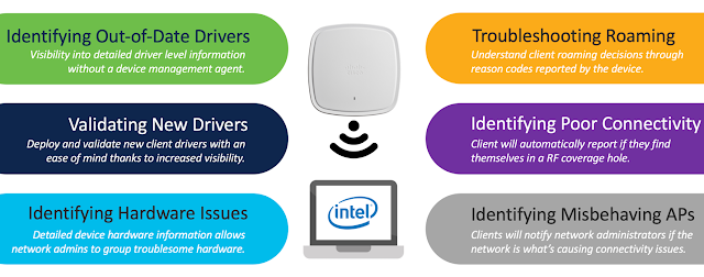
More than just telemetry, Intel Connectivity Analytics provides intelligent reports that allow network administrators to understand what to do next for any problem and ensure a great user experience in even the most complex wireless deployments by addressing the use cases in Figure 1 below.

Cisco and Intel, Cisco Wireless, Cisco Connectivity Analytics, Cisco Exam Prep, Cisco Exam Preparation, Cisco Career
Figure 1. Intel Connectivity Analytics Use Cases

Six Intelligent Reports to Solve All Your Problems

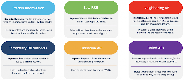
Intel Connectivity Analytics generates six reports (Figure 2) in real-time based on information forwarded by wireless clients to the AP and then Cisco Catalyst controller or Meraki Dashboard that directly addresses the use cases depicted in Figure 1.

Note: Station information, Neighboring AP, and Failed AP reports are generated at client association, while others are triggered when the situation arises.

Cisco and Intel, Cisco Wireless, Cisco Connectivity Analytics, Cisco Exam Prep, Cisco Exam Preparation, Cisco Career
Figure 2. Intel Connectivity Analytics Reports Details

Identifying out-of-date Driver, Validating New Drivers, and Identifying Hardware issues:

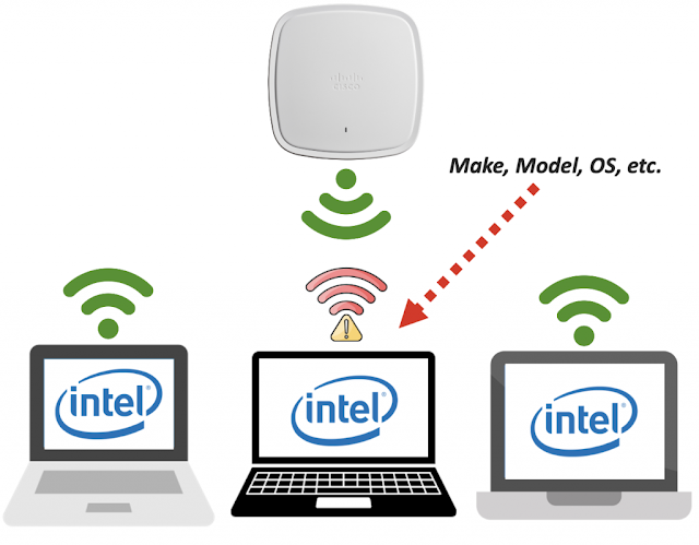
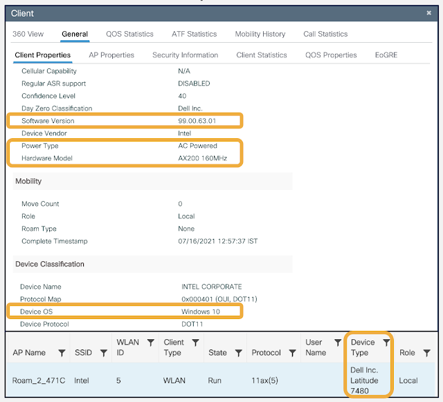
The Station Information report provides network administrators with driver-level client information that would not have been available in typical telemetry. This additional information allows network administrators to pinpoint the specifications such as software driver or hardware model that clients experiencing poor Wi-Fi are on and target just them.

Cisco and Intel, Cisco Wireless, Cisco Connectivity Analytics, Cisco Exam Prep, Cisco Exam Preparation, Cisco Career
Figure 3. Identifying Hardware Issues with Intel Connectivity Analytics

Cisco and Intel, Cisco Wireless, Cisco Connectivity Analytics, Cisco Exam Prep, Cisco Exam Preparation, Cisco CareerFigure 4. Station information or Device Classifier WebUI Output on the Catalyst 9800 Controller

Outdated wireless drivers can also be a common culprit for a poor wireless experience. The station information report gives network administrators peace of mind when rolling out software updates knowing they have complete visibility on the Catalyst or Meraki controller.

Cisco and Intel, Cisco Wireless, Cisco Connectivity Analytics, Cisco Exam Prep, Cisco Exam Preparation, Cisco Career
Figure 5. Identifying Out of Date Drivers (Left) & Validating New Drivers (Right) with Client Connectivity Analytics

Troubleshooting Roaming:

When a client roams, it’s entirely a wireless client’s decision to do so, and the network has little to no visibility into the reason. Thanks to Intel Connectivity Analytics, we have reports that will share these insights with reason codes such as Low RSSI, 11v Recommendations, Missed Beacons, and Better AP. Based on these insights, a network administrator can determine whether the suspicious client roam was for a legitimate reason or not.

Cisco and Intel, Cisco Wireless, Cisco Connectivity Analytics, Cisco Exam Prep, Cisco Exam Preparation, Cisco Career
Figure 6. Troubleshooting Roaming with Client Connectivity Analytics

Cisco and Intel, Cisco Wireless, Cisco Connectivity Analytics, Cisco Exam Prep, Cisco Exam Preparation, Cisco Career
Figure 7. Roaming Scenario Report WebUI Output on the Catalyst 9800 Controller

Identifying Poor Connectivity:

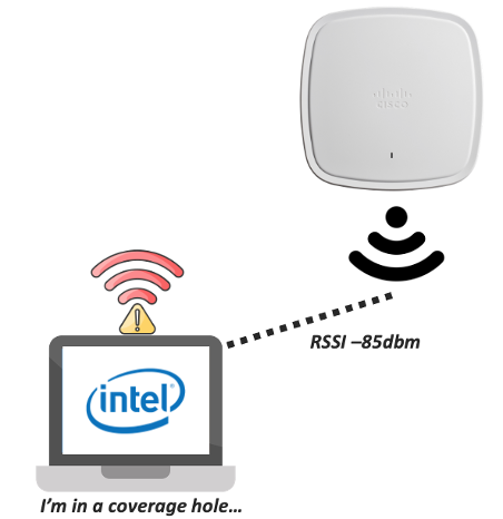
When a wireless client’s RSSI falls below a certain threshold, a Low RSSI report will be generated to alert network administrators about possible coverage holes. These issues can then be proactively addressed by increasing the Tx power on an AP, deploying additional APs, and monitoring if more Low RSSI reports are generated.

Cisco and Intel, Cisco Wireless, Cisco Connectivity Analytics, Cisco Exam Prep, Cisco Exam Preparation, Cisco Career
Figure 8. Identifying Poor Connectivity with Client Connectivity Analytics

Identifying Misbehaving APs:

Intel Connectivity Analytics supported clients will report if an AP is broadcasting invalid IEs in their beacons, probes, and association responses that would cause connectivity and security concerns. In fact, failed AP reports will even go deeper at the packet level and highlight problematic authentication frames, association frames, or missing response frames.

Intel Connectivity Analytics can even detect rogue AP behavior with the Unknown AP report, which is used to identify and flag rogue BSSID’s (BSSIDs that are not part of an earlier neighbor report)

Cisco and Intel, Cisco Wireless, Cisco Connectivity Analytics, Cisco Exam Prep, Cisco Exam Preparation, Cisco Career
Figure 9. Identifying Misbehaving APs with Client Connectivity Analytics

Cisco and Intel, Cisco Wireless, Cisco Connectivity Analytics, Cisco Exam Prep, Cisco Exam Preparation, Cisco Career
Figure 10. Unknown AP Report CLI Output on the Catalyst 9800 Controller

How Does It Work?

Intel Connectivity Analytics uses a Cisco Catalyst 9800 series controller and Catalyst 9100 access point topology from the Cisco Enterprise Network side. The controller enables the features by default on a per WLAN basis. Intel Connectivity Analytics supported client sends the driver-level telemetry back to the access point, which is then processed and presents users with intelligent reports and insights.

Cisco and Intel, Cisco Wireless, Cisco Connectivity Analytics, Cisco Exam Prep, Cisco Exam Preparation, Cisco Career
Figure 11. Intel Connectivity Analytics Topology

For a technical understanding, refer to the following points:

1. All Intel Connectivity Analytics packet exchanges are protected using PMF for security purposes.
2. Cisco network running IOS XE 17.6.1 or later with the feature enabled will advertise Intel Connectivity Analytics feature support in the Beacon frames.
3. Supported Intel clients will detect and begin forwarding telemetry periodically via a protected Action frame.

As you can see, Intel Connectivity Analytics provides network administrators with granular client-side telemetry in an agentless package at a level never seen in the past. With its wide range of use cases, minimum day 0 requirements, there’s no reason why you wouldn’t leverage such a powerful wireless analytics solution! Take the wireless experience of your network to the next level with Intel Connectivity Analytics today!

Source: cisco.com

Thursday, 23 September 2021

Cisco teams up with Meshtech and launches Application Hosting for brand-new Asset Tracking IoT portfolio

Application Hosting on the Catalyst 9100 series access points allows organizations of all sizes to run IoT applications from the edge. As organizations integrate and deploy IoT services across their networks, the ability to optimize workflows, streamline IoT application changes, and simplify critical processes right out of the box, is essential. This includes having the ability to monitor IoT deployments end-to-end, as well as ongoing device and IoT network management. This is precisely why Cisco is developing integrations with vendors like Meshtech.

Cisco and Meshtech deliver seamless integration

Meshtech, based in Norway, develops IoT solutions that are used in smart buildings, healthcare, transportation, manufacturing, and more. Its portfolio includes a suite of sensors, asset monitoring, and control systems that are used for environmental monitoring, asset tracking, and usage analytics.

Read More: 300-715: Implementing and Configuring Cisco Identity Services Engine (SISE)

With Cisco’s Application Hosting capabilities, Meshtech devices communicate directly with the Cisco Catalyst access point. Application Hosting doesn’t replace the Meshtech application but rather it eliminates the need for additional hardware while adding additional device management features.

IT teams retain the same visibility into key performance indicators across Meshtech sensors including humidity levels, movement, and temperature. With Application Hosting, they gain additional visibility and control on the Cisco platform. This includes the status of IoT devices, placement of sensors, as well as the ability to push application updates. Together, the integrated solution provides advanced visibility, control, and support across the application lifecycle.

Cisco Teams, Cisco Prep, Cisco Tutorial and Materials, Cisco Guides, Cisco Learning, Cisco Career, Cisco Preparation
Meshtech dashboard

How it works


As with all Application Hosting solutions on the Catalyst platform, the solution takes advantage of Docker-style containers to host the application directly on the access point. Further simplifying the solution is its use of industrial Bluetooth Low Energy (BLE). Meshtech’s BLE module makes use of the integrated USB port in the Cisco Catalyst access points to control and manage any of Meshtech’s IoT devices.

Cisco Teams, Cisco Prep, Cisco Tutorial and Materials, Cisco Guides, Cisco Learning, Cisco Career, Cisco Preparation

On the Meshtech side, a containerized version of its management application is hosted on the Cisco Catalyst access point. This allows Meshtech IoT devices communicate and share valuable data while also allowing IT Teams to control actions directly from the Cisco wireless network.

The below diagram showcases the breadth of Meshtech IoT devices supported with Application Hosting on Catalyst Access Points.

Cisco Teams, Cisco Prep, Cisco Tutorial and Materials, Cisco Guides, Cisco Learning, Cisco Career, Cisco Preparation
Meshtech solutions

Easy deployment and management


To summarize, Application Hosting enables the elimination of IoT overlay networks, which simplifies deployments and management while reducing costs. The Cisco Catalyst Access Point does all the heavy lifting by driving the application at the edge. With Application Hosting, there’s no need for additional IoT hardware, installation, or maintenance, everything is integrated.

Thursday, 3 June 2021

Too Fast Too Furious with Catalyst Wi-Fi 6 MU-MIMO

Servicing many clients that are using small packets with non-Wi-Fi 6 is inefficient because the overheads incurred by the preamble and other mechanisms tend to dominate. OFDMA is ideally suited for this scenario because it divides up the channel and services up to 37 users (for 80MHz bandwidth) simultaneously, which amortizes the overhead. OFDMA improves system efficiency, but it does not necessarily improve throughput.

MU-MIMO (Multi-User, Multiple input, Multiple output) creates spatially distinct separate channels between the transmitter and each of a small number of receivers such that each receiver hears only the information intended for itself, and not the information intended for other receivers. This means that the transmitter can, by superposition, transmit to a few receivers simultaneously, increasing the aggregate throughput by a factor equivalent to the number of receivers being serviced.

Cisco’s Catalyst 9800 series WLC with IOS XE 17.6.1 (currently Beta) introduces futuristic Access Point scheduler design, which efficiently serves multiple clients at the same time. This is done while creating least level of sounding overhead, which in turn yields data rates close to PHY rate even in dense environment. These advancements are currently supported on Catalyst 9130 and Catalyst 9124 series Access Points. Let’s first understand MU-MIMO concepts and then evaluate its performance.

Beamforming and MU-MIMO

Beamforming radio waves using an array of phased antennas has been known for decades. More recently the principles have been used to produce MU-MIMO where the concept of multiple simultaneous beams to provide independent channels for each of the users.

Similar principles apply in the audio domain where speakers can be phased to direct sound to a particular location. The idea is to adjust the phases of each speaker such that the sound adds constructively at the point where the listener is, and destructively at all other locations.

Consider a sound, Sr , played through an array of four speakers with the sound for each speaker adjusted by a phasor Q1r through Q4r so that the signal strength at the red listener, Lr is maximized, and the signal strength at the blue listener Lb is minimized.

Cisco Certification, Cisco Learning, Cisco Guides, Cisco Career, Cisco Preparation

Cisco Certification, Cisco Learning, Cisco Guides, Cisco Career, Cisco Preparation

Using superposition, we can take each message, impose the appropriate phase adjustment, and add the signals just before they go into the speakers. This way we can send two different messages at the same time, but each listener will hear only the message intended for them.

Cisco Certification, Cisco Learning, Cisco Guides, Cisco Career, Cisco Preparation

Note the importance of spatial separation – Lb and Lr are hearing their respective messages because the phasors were optimized to deliver each sound to their specific location. If one of the listeners moves from his position, he will no longer hear his message.

If a third person enters the picture and stands close to the speakers, he will hear the garbled sound of both messages simultaneously.

Consider this in the context of Wi-Fi where the speakers are replaced by antennas and the signal processing to control the phasors, and generate digital messages at a certain data rate, is done in the AP. Since both messages can be transmitted simultaneously one could theoretically double the aggregated data rate. The same approach can be used to service more clients simultaneously, so where is the limit? Practically, there are limits in the accuracy that the phasors can be set, there are reflections that cause “cross talk” and other imperfections that limit the gains in throughput that can be achieved.

Sniffing in the context of MU-MIMO is more complicated because of the spatial significance.  Note that placing a sniffer close to the AP will achieve the same garbled message effect we discussed earlier. The sniffer probe must be placed physically close to the device that is being sniffed, and generally one sniffer probe is required for each device.

System Overview and Test infrastructure


In this MU-MIMO test, we are using the octoScope (now part of Spirent) STACK-MAX testbed. On the infrastructure side, Cisco’s Catalyst 9800 WLC running IOS XE 17.6.1 (Beta code) and Catalyst 9130 Access point is used. The C9130 AP supports up to 8×8 uplink and downlink MU-MIMO with eight spatial streams. The Pal-6E is Wi-Fi 6 capable and can simulate up to 256 stations or can act as Sniffer probe.

Cisco Certification, Cisco Learning, Cisco Guides, Cisco Career, Cisco Preparation

The STApal is a fully contained STA based upon the Intel AX210 chipset, running on its own hardware platform. All the test chambers are completely isolated from the outside world, and signal paths between them are controlled using fully shielded attenuators, so that reliable and repeatable measurements can be made. The chambers are lined with an RF absorptive foam to significantly reduce internal reflections and prevent standing waves.

For this MU-MIMO test we are using up to 4 STA’s. RF path connects signals from the C9130 AP through to individual STAs. We are using the multipath emulator (MPE) in LOS, or IEEE Channel Model A mode. Each pair of antennas is fed into a group of four clients as shown in the diagram below. We have seen that spatial separation is a requirement for successful MU-MIMO operation. This is achieved by placing antennas in the corners of the anechoic test chamber to get the best spatial separation. This allows four independent MU-MIMO streams to STAs in the four groups of four.

Cisco Certification, Cisco Learning, Cisco Guides, Cisco Career, Cisco Preparation

Practical testing


To demonstrate the MU-MIMO gains we placed C9130 AP in the center of the chamber and ran downlink UDP traffic to the STAs attached to the antennas in the box corners.

First, we did this with MU-MIMO switched off and started with one STA. We noted that the throughput was just a little over 1000 Mbps, a little less than the 1200 Mbps of the PHY rate.  After 20 seconds we introduced another STA and saw that the aggregate throughput stays at the 1000 Mbps, but that the two STAs share the channel and each STA is achieving 500 Mbps. 20 seconds later we introduced a third STA. Again the aggregate throughput stays the same at 1000 MBps, and the three STAs share the channel to get a little over 300 Mbps each. Introduction of the fourth STA follows the same pattern with the aggregate remaining unchanged, and each STA receiving 250 Mbps.

Cisco Certification, Cisco Learning, Cisco Guides, Cisco Career, Cisco Preparation

We repeated the experiment, this time with MU-MIMO switched on.

Starting with one STA we achieved the familiar 1000 Mbps. After 20 seconds we introduced the second STA and observed the aggregate had increased to 2000 Mbps which is significantly higher than the PHY rate. We also noted that each STA is still receiving nearly the 1000 Mbps it was before.  Unlike the previous experiment where the STAs shared the channel, in this experiment they are each able to fully utilize their own channel independently of each other.

Cisco Certification, Cisco Learning, Cisco Guides, Cisco Career, Cisco Preparation

Adding a third STA increased the aggregate to 2200 Mbps. Each of the three STAs was still receiving 730 Mbps. Addition of a fourth STA results in aggregate throughput of 2100 Mbps with each STA receiving 525 Mbps, a two-fold increase over Single User operation.

The graph below summarizes the results.

Cisco Certification, Cisco Learning, Cisco Guides, Cisco Career, Cisco Preparation

Verdict


MU-MIMO exploits the spatial separation of receivers to direct independent messages to each of the receivers simultaneously. This allows for much more efficient use of the medium and increases the aggregate data that the network can deliver. Catalyst 9130 AP’s pioneering scheduler design offers superior throughput gains in Multiuser transmission scenarios. This is an outcome of higher MCS rates, low sounding overhead  and efficient dynamic packet scheduling.

DL and UL MU-MIMO along with OFDMA are enabled by default on a WLAN. These features are available on 9800 series wireless controllers on existing releases but the above discussed enhancements will be available from 17.6.1 (currently Beta) release onwards.

Source: cisco.com

Thursday, 27 August 2020

Cisco DNA Spaces Indoor IoT Services with Wi-Fi 6 – Delivering Business Outcomes at Scale

Organizations today are facing unprecedented times, and the need to digitize physical spaces has never been more important.

To adapt to these new challenges, enterprises must shift toward a new, open and unified ecosystem that both (1) supports delivering outcomes at scale and (2) continues to provide the enterprise with control of their infrastructure and solution stack.

Cisco’s wireless infrastructure with Cisco DNA Spaces is a powerful framework to enable this new requirement. Wireless access points have evolved from being used for connectivity to being a sensor enabling location services –  and Cisco’s Wi-Fi 6 Certified Catalyst 9100 access points powered by Cisco’s Catalyst 9800 controllers can now serve as a powerful gateway for not just Wi-Fi devices but also BLE asset tags, beacons, and other IoT end devices.

With *Cisco DNA Spaces Indoor IoT Services, customers can take their wireless beyond connectivity, digitize their physical spaces, and gain insights on the behavior of people, and now things. Currently supporting at least 500 million mobile devices, processing over 1 trillion location updates, and live across over 1 million access points, Cisco DNA Spaces continues to scale into digitizing enterprises across various industries.

Enabling Multiple Use Cases through an Open, Unified Platform


Location services solutions today face major challenges with complexity and limited ability to scale. There is a fragmented market of proprietary solutions where new applications would require disparate hardware and software, limiting flexibility and reusability.

Vendor-specific apps and hardware mean that there are separate touchpoints for monitoring and support, resulting in disjointed support models. As customers discover more use cases and deploy more IoT devices, they run into management pains with vendor lock-in and limited scalability.

Cisco Networking, Cisco DNA Center, Wireless and Mobility, Cisco Exam Prep, Cisco Tutorial and Material

To overcome this complexity and cost, we are excited to announce Cisco DNA Spaces *Indoor IoT Services – which provides an open and unified platform for ordering IoT devices, onboarding and configuring devices, and connecting to industry-specific applications to enable business outcomes.

This offering will help customers deploy their applications rapidly, at scale, and at a significantly lower total cost of ownership (TCO).  This empowers enterprises to deploy multiple use cases such as asset management, room finding, space utilization, environmental monitoring, employee safety, and more, all enabled through a single middleware layer.

With Cisco DNA Spaces Indoor IoT Services, customers can deploy a broader spectrum of end devices, all without having to deploy separate gateways.

Cisco Networking, Cisco DNA Center, Wireless and Mobility, Cisco Exam Prep, Cisco Tutorial and Material

The IoT Device Marketplace features a broad spectrum of supported end devices ready for customers to order and deploy. Customers have a wide choice of specialized beacons, tags, wristbands, badges, sensors, and other devices that are ready to deploy.

They can choose these devices based on their required use case, technology, form factor, and price. The device vendors are validated and are integrated into Cisco DNA Spaces end-to-end support model.

Cisco Networking, Cisco DNA Center, Wireless and Mobility, Cisco Exam Prep, Cisco Tutorial and Material

Customers can discover and order end devices through the IoT Device Marketplace.

Cisco DNA Spaces also has an ecosystem of partner applications that are easy to activate. The Cisco DNA Spaces App Center features industry specific partner applications that leverages the location data from Cisco DNA Spaces, delivered over the Firehose API, to drive business outcomes across healthcare, workspaces, retail, hospitality, education, and manufacturing.

Cisco Networking, Cisco DNA Center, Wireless and Mobility, Cisco Exam Prep, Cisco Tutorial and Material

Discover vertical specific partner applications on the Cisco DNA Spaces App Center.

Wi-Fi 6 Access Points with Dynamic Gateways


Cisco’s Wi-Fi 6 certified Catalyst 9100 access points can now host the Cisco DNA Spaces Advanced Gateway, deployed through Indoor IoT Services. This gateway enables management of BLE beacons and asset tags. The access points also come standard with a BLE radio, allowing them to scan, detect telemetry, transmit, and receive location information from various BLE end devices.

This decouples devices & applications, meaning customers can enable multiple applications with a wide range of devices, without having to worry about vendor compatibilities. This also replaces the need for overlay networks, and customers won’t have to deploy separate gateways.

Cisco Networking, Cisco DNA Center, Wireless and Mobility, Cisco Exam Prep, Cisco Tutorial and Material

End-to-End as a Service


Cisco DNA Spaces Indoor IoT Services is an end-to-end as a service offering that greatly simplifies the activation, configuration, monitoring and management of IoT end devices from different vendors. You can discover devices from your network, activate them, and group these devices by assets, use cases and types of devices.

Device management is made simple with the ability to apply policy-based configurations to the device groupings.

Cisco Networking, Cisco DNA Center, Wireless and Mobility, Cisco Exam Prep, Cisco Tutorial and Material

Apply policies to device groups, based on use case or asset.

End-to-end monitoring & support capabilities are also being expanded to include the end devices, in addition to Cisco DNA Spaces location data, access points, and partner applications. Monitoring will now include device battery level, last heard, and firmware to ensure that your end devices are working optimally.

Cisco Networking, Cisco DNA Center, Wireless and Mobility, Cisco Exam Prep, Cisco Tutorial and Material

Monitor devices through the dashboard and get proactive alerts on which devices require attention.

Wednesday, 8 January 2020

Wi-Fi 6E: The evolution of next generation wireless access

Networking, 5G, Enterprise Networks, Wireless, Wireless and Mobility, Cisco Prep, Cisco Certification, Cisco Online Exam

Wi-Fi 6 just arrived, bringing better speed and more capacity to wireless networks. And soon it’s going to get even better, thanks to the FCC opening up of all-new 6 GHz frequencies for Wi-Fi 6. The name of this extension to the standard: Wi-Fi 6E.

When the new 1.2 GHz of spectrum (500 MHz in the EU) starts getting built into devices later this year, it will unleash new potentials for networks, and help them meet the growing demand for high-performance connectivity.

The Need for More Unlicenced Spectrum


Moving from one Wi-Fi generation to the next – currently in the sixth generation – all wireless devices share the crowded 2.4 and 5 GHz bands. They are constantly competing for bandwidth. The limited spectrum and channels in those bands cause significant issues for users. There are very few non-overlapping 80 MHz or 160 MHz (in 5 GHz band) channels to prevent interference caused by devices on overlapping channels. In fact, it’s almost impractical to enable these wide band channels in dense environments such as venues with hundreds of access points. Besides, the 20 MHz and 40 MHz channels are not wide enough to support high data throughput for bandwidth-intensive applications.

These problems have been exacerbated by the proliferation of wirelessly connected IoT devices and data growth. For example, Wi-Fi and mobile devices will account for more than 75 percent of all Internet traffic by 2022.

We need more unlicensed spectrum to deliver on the Wi-Fi brand promise, and that’s what the new 6 GHz frequencies will deliver.

The Promise of Wi-Fi 6E


To keep unlicensed Wi-Fi devices running in the 6 GHz band from interfering with incumbent users of the band such as microwaves links, the FCC is proposing some technical restrictions. These rules divide the overall spectrum into 4 separate bands with their own boundaries. For example, a Wi-Fi device could only operate indoors at low power in order to ensure unlicensed services can coexist safely with existing incumbents. (Figure 1)

Networking, 5G, Enterprise Networks, Wireless, Wireless and Mobility, Cisco Prep, Cisco Certification, Cisco Online Exam
Figure 1 – 6 GHz Wi-Fi Channels

Wi-Fi 6E brings the following improvements and enables important use cases:

1. More spectrum

An additional 1.2 GHz spectrum, twice the size of the current Wi-Fi bandwidth, offers more non-overlapping channels i.e. 59 additional 20 MHz channels  And only Wi-Fi 6 devices are allowed in this new spectrum. No legacy (Wi-Fi 5 or earlier) devices will have access to it. Wi-Fi 6 not only gets the additional bandwidth of Wi-Fi 6E, it uses that bandwidth more efficiently, which makes this new spectrum great for solving capacity problems in large public venues, such as concert venues or sports stadiums. This not only enables better user experience but opens the gateway for quality live streaming connections.

2. Higher throughputs

As envisioned, Wi-Fi 6E makes available large contiguous blocks of spectrum. With 14 additional 80 MHz and 7 additional 160 MHz wide channels, it allows for high-throughput and concurrent data transmission. This enhances applications that require high bandwidth such as augmented and virtual reality (AR/VR) and real-time immersive gaming on Wi-Fi 6 devices. It will further the current Wi-Fi 6 capabilities for the next generation of learning where every student in a classroom or in a school can use a VR headset for their education at the same time.

3. Lower latency

The high frequency spectrum of Wi-Fi 6E opens up entirely new horizons for ultra-low latency and emerging data-intensive applications and services, such as telehealth. Wi-Fi 6E is able to provide reliable and consistent low-latency connectivity for critical applications that can’t afford data delays. This allows, for example, patients to connect virtually with doctors and get real-time diagnostics on their high-quality 3D CAT exam or MRI.

All in all, Wi-Fi 6E expands the horizon of user connectivity, opens opportunities for emerging use cases, and enables enterprises to push boundaries with innovations. Cisco is actively partnering with the regulatory agencies working on Wi-Fi expansion. We will keep you updated as regulators finalize the operational requirements. Watch for product announcements from Cisco that will seize upon this new spectrum.