Friday, 20 August 2021

Cisco Ultra Cloud Core Repels Pro Hackers

Cisco Ultra Cloud, Cisco Prep, Cisco Tutorial and Material, Cisco Career, Cisco Guides, Cisco Preparation

Security is critical when developing new technology and that’s never going to change. Those with ill intent work 24 hours per day, seven days per week to discover vulnerabilities in servers, routers, and security devices that can be exploited. Whether it’s to release viruses or collect millions of dollars in ransomware, tech criminals will never stop committing crimes. The best we can do is protect our hardware, software, and firmware with zero trust and the utmost cyber security built in as a foundational concept rather than bolted on later as an afterthought.

With security at the forefront of everything we do, Cisco recently collaborated in a 5G hackathon with Finnish Transport and Communications Agency Traficom and Junction, an international non-profit ethical hacking and tech community which hosts the annual 48-hour event in Helsinki. This hackathon, held June 18-20, 2021, brought together entrepreneurs, developers, designers, and students from around the globe with a goal of helping local and multinational companies build viable, secure solutions to real-world challenges in 5G networks and services.

Cisco participated in this event, alongside Ericsson, Nokia and others, with an offer of 10,000 Euros in prize money to try to hack into the Cisco Ultra Cloud Core. Some of world’s leading cyber security professionals were asked to search for hidden flags and discover/document any vulnerabilities found in our 5G core. We knew going in that collaboration between vendors, researchers, regulatory authorities, solution developers, and the ethical hacker community would benefit everyone involved when building secure networks and services.

To set the stage for this event, appropriately named “I Bet You Can’t Get In”, the Mobility Technical Marketing Engineer (TME) group constructed this challenge in a way that created a bona fide environment in which to work while still protecting our core lab assets from nefarious activity. The mobility TME began by building a VMware cluster fully isolated from the lab with internet connectivity via a Cisco Adaptive Security Virtual Appliance (ASAv) firewall. Once we had a secure, remote-access sandbox environment prepared, a second team worked to bring up the 5G core on the VMware cluster.

More than 80 global participants organized into teams joined the Cisco challenge and were given access to the test lab through Anyconnect VPN. The challenge was then broken up into three primary facets: collecting user traffic to find the “needle” (a motivational quote from Steve Jobs), obtaining Command-Line Interface (CLI) access to the User Plane Function (UPF) to discover administrator account details, and exploiting a REST API to retrieve any information possible.

On a Friday evening (now that’s dedication!), we led the kickoff meeting to lay out the challenge via a live Webex session. The event commenced at 8 pm local time and the teams of hackers worked through the night and into the morning. On Saturday we held a check-in meeting to examine the progress they’d made. At that time, many of the hackers had given up. Aside from port scan results, no one had managed to gain access or even come close to meeting the challenge. Our team then dropped a few hints such as revealing the password of the UPF’s operator account. Following this hint, two teams utilized the monitor interface tool to locate the Steve Jobs quote, thus solving the first challenge.

The second part of the challenge, SSH CLI interfaces on 5G NFs, held its own, as did the third portion involving REST APIs. The only “hardening” involved was to disable SSH access to the Kubernetes (K8s) nodes, and in the end, only the first challenge was solved (buried in http and gtpu).

Finally, Team cKobclz79 was awarded the first prize of 5,000 Euros based on their ability to solve the first challenge and find the quote. Team Steamy Jofa was awarded the second prize of 3,000 Euros based on continued effort and overall tenacity. However, no other teams achieved enough progress to earn the third prize, so we decided to donate that money to a local Finnish charity.

At the conclusion of the event, we had a chance to speak with the winning three-member Team cKobclz79. As alumni of Aalto University in Finland, they frequently receive notifications of various events involving their alma mater. With an interest in misusing APIs and searching for design flaws in network architecture, they felt a 5G cybersecurity hack offered the perfect chance to keep up with the trends and technologies and acquire penetration testing skills in the industry.

The team began by scanning the network to locate an entry point, and once they found some hosts with open ports, they started searching for vulnerabilities. While digging deeper and sniffing internal traffic, they expanded their knowledge of 5G architecture, learning new terms and better understanding connections between nodes. The team found different parts of the challenge difficult due to having divergent backgrounds. One member struggled to understand the architecture and documentation but had no trouble with the tech stack, another wasn’t sure if they were on the right track because of so many hosts, while the third found several attack points that were not required for the challenge but nevertheless interesting.

With an attitude that no technology is truly safe, the team knew most security vulnerabilities reside in misconfigurations and leaked internal tech stack information, but during initial reconnaissance, they gained access through a system design flaw. They found that a websocket in a staging server would allow them to send commands. A check of other ports then revealed a Docker image whose source code provided a window into how commands were sent. By performing remote code execution, they established the reverse shell as root. This allowed them to install tools to scan the network and examine internal traffic. Enumerating the internal network gave them insight into other nodes based on the 5G architecture documentation provided to start the challenge.

Cisco Ultra Cloud, Cisco Prep, Cisco Tutorial and Material, Cisco Career, Cisco Guides, Cisco Preparation

The team then found a Docker registry from which they could pull the image and get the code for CLI access. This websocket GUI allows system administrators to connect to cluster manager and maintain the operation of Ultra Cloud Core.

Cisco Ultra Cloud, Cisco Prep, Cisco Tutorial and Material, Cisco Career, Cisco Guides, Cisco Preparation

Following an internal network scan, they found the K8s master node that could be reached from cluster manager. With no firewall to block communication from cluster manager to K8s master, they discovered that a service account credential to connect to the K8s cluster would have allowed them to run commands using kubectl they installed in cluster manager. They could then disrupt existing services or deploy malicious images to trick customers into connecting to them since all services are deployed, controlled, and managed by K8s master.

This event was a huge success and every participant derived value from it. Although we can’t definitively say that Cisco Ultra Cloud Core can’t possibly be hacked, this experience proved that it’s far more difficult than one might imagine. The event allowed technology vendors to put their 5G core to the test, and although these dedicated hackers did their best, they couldn’t hack our core.

As security becomes an increasing concern with the proliferation of 5G and IoT technologies, this event served as a great learning experience for the Cisco mobility team. As new threats exploit the wider footprint of these emerging technologies, challenges like this serve as one of many methods for gaining insights into future attacks so that we can design and build more resilient networks and services.

Source: cisco.com

Thursday, 19 August 2021

Simply Faster than the Rest, Cisco Wi-Fi 6 + Multigigabit Switching

Cisco Prep, Cisco Tutorial and Material, Cisco Learning, Cisco Preparation, Cisco Guides, Cisco Study Material
It’s a typical day, and as you’re mindlessly scrolling through your phone again, *ding*, a notification reads, “Flying cars will be available for purchase in just one year!”.

Wow, that’s exciting!

But would you be surprised?

The fact is, technology is advancing so fast that before we can adjust to the current innovation, a better version is already available. Just look at where we were with virtual reality, self-driving cars, and IoT smart homes only a few years back. The point is, our expectation for what is possible has never been higher, and as a technology fanatic, life is good!

But while we’re busy geeking out, let’s not forget that all this upcoming innovation requires an equally powerful network infrastructure to support it. For example, let’s look at 8K VR gaming, a technology that’s right around the corner and will require a minimum of 1 Gbps for gameplay and above 2 Gbps for an optimal experience. With a growing thirst for technology to provide a more HD, a more next-gen, and a more seamless experience, we can expect that the required data consumption will skyrocket as well.

The question is no longer whether innovation is coming but if your network can handle it.

Next Level Wireless Speeds with Multigigabit Switching

Wi-Fi 6, with all its glory, has been the star of the networking show since the launch of Cisco’s Catalyst wireless access point (AP) product line. From our flagship Catalyst 9130 Access Point boasting a ridiculous max PHY of 5.37 Gbps down to the small Catalyst 9105, they’re truly the gold standard of enterprise wireless.

But what if I told you there is a way to further enhance their already incredible prowess?

By simply combining Cisco Catalyst APs with Catalyst Multigigabit Switching, we can witness what can only be described as network performance at its finest. A bold statement, but I can prove it by showing you the throughput numbers tested within Cisco’s wireless lab using a Catalyst 9130 Wi-Fi 6 AP on software version 17.5.1 and a Catalyst 9300 multigigabit switch.

Numbers Speak for Themselves

But first, let’s take a step back; if we connect a Catalyst 9130 AP to a gigabit switch, the 5.38 Gbps max PHY is actually significantly bottlenecked as the throughput capabilities become limited from the wired side.  With this topology, we achieved an average throughput of just below 1 Gbps using the IxChariot performance testing tool.

Simply Faster than the Rest, Cisco Wi-Fi 6 + Multigigabit Switching
Figure 1. 3x Intel AX200 endpoints on 2.4 GHz at 20 MHz and 15x Intel AX200 on 5GHz at 80 MHz

Don’t get me wrong; these data rates are fast; it’s just that it could be so much faster!

To properly enjoy the true power of Wi-Fi 6, we connected the same Catalyst 9130 AP to a ten-gigabit port of a multigigabit switch and were able to achieve over 2 Gbps consistently.

Simply Faster than the Rest, Cisco Wi-Fi 6 + Multigigabit Switching
Figure 2. 3x Intel AX200 endpoints on 2.4GHz at 20MHz and 3x Intel AX200 on 5GHz at 80MHz

With the only differing factor being the multigigabit switch, we were able to over double the throughput! With these blazing fast throughput numbers combined with Wi-Fi 6’s OFDMA and MU-MIMO, you’ve got yourself a wireless powerhouse that’s unmatched by any other vendor in the world and is ready for whatever the future throws at it.

Source: cisco.com

Tuesday, 17 August 2021

Cisco Catalyst 8000V, the Cloud-Smart Router, Powers Secure SD-WAN for Multicloud and SaaS

Cisco SD-WAN, Cisco Tutorial and Material, Cisco Career, Cisco Study Materials, Cisco Preparation, Cisco Guide

Cisco Catalyst 8000V Edge Software was launched in November 2020 as an evolution of the widely adopted Cisco Cloud Services Router (CSR) 1000V, which is deployed by more than 5,000  customers globally.  As the successor to the widely adopted CSR 1000V, the Catalyst 8000V offers the next generation of secure multicloud networking and cloud-smart capabilities in software, required by enterprise workloads for the public cloud and SaaS.  As public cloud solutions become more ubiquitous, with Gartner predicting spending on public cloud services to grow 23.1% in 2021 to $332.3 billion, customers will look to accelerate their journey to multicloud with a trusted enterprise-grade and cloud-smart solution.

Cisco SD-WAN, Cisco Tutorial and Material, Cisco Career, Cisco Study Materials, Cisco Preparation, Cisco Guide
Figure 1: Catalyst 8000V, the Cloud-Smart Router

Powering secure multicloud networking, the Catalyst 8000V, can integrate with cloud formation templates, DevOps tools, Cisco’s vManage Controller, and be deployed by enterprises to programmatically connect to multicloud architectures as shown in Figure 1.  Automation tools, such as Terraform, are also widely popular with Catalyst 8000V, allowing customers to easily manage their infrastructure deployment.  Cisco SD-WAN Cloud OnRamp integrates with the Catalyst 8000V to offer an easy-to-use, end-to-end solution.

Evolution of Cisco’s Cloud Router The CSR 1000V was launched to bring the industry-leading Cisco IOS® XE Software networking capabilities to address virtualization and cloud needs.  As customers’ needs evolved, a smarter solution was needed, which is where the Catalyst 8000V was conceived.  A single, ‘cloud-smart’ router which powered customers multicloud networks and interoperates  across disparate deployment environments was needed.

Cisco SD-WAN, Cisco Tutorial and Material, Cisco Career, Cisco Study Materials, Cisco Preparation, Cisco Guide
Figure 2: Evolution of Cisco’s Cloud Router

A simple cloud consumption experience was also foundational to the definition of the Catalyst 8000V, as licensing was simplified with the launch of the Catalyst 8000V using standardized Cisco DNA licenses.

Cisco SD-WAN, Cisco Tutorial and Material, Cisco Career, Cisco Study Materials, Cisco Preparation, Cisco Guide
Figure 3: Catalyst 8000V is the anchor tenant in Secure SD-WAN for Multicloud and SaaS

Catalyst 8000V, the Cloud-Smart Router

Purpose built for the cloud, the Catalyst 8000V provides a smart, enterprise-ready, and simplified experience for easy deployment as shown in Figure 3. Customers with a “Cloud First” mindset should consider Cisco’s cloud-smart router,  which has enjoyed great success with various SD-WAN Cloud OnRamp use cases for site to cloud automation for AWS, Microsoft Azure, Google Cloud, and Ali Cloud.

Acting as the anchor tenant, the Catalyst 8000V underpins forward looking solutions such as software-defined cloud interconnect (SDCI), on-demand global networks, and colocation solutions, with partners like Megaport and Equinix .  Figure 4 shows how Catalyst 8000V, with vManage, can be deployed and managed across the different use cases in a single, intuitive dashboard.  The Catalyst 8000V simplifies the complexities in managing customers varied network requirements and operational approaches.

Cisco SD-WAN, Cisco Tutorial and Material, Cisco Career, Cisco Study Materials, Cisco Preparation, Cisco Guide
Figure 4: Catalyst 8000V Integrates into Multiple Workflows

For insights into the performance of the Catalyst 8000V, Cisco vAnalytics is an option, which can provide customers with contextual network visibility and actionable insights into device and fabric performance and events. The visibility makes it easier than ever to spot anomalies in the network and to perform intelligent capacity planning.

Moving forward, as enterprises workloads evolve to require consistent secure access to public cloud providers, SaaS vendors for application optimization, colocation, SDCI, and traditional on-prem use cases, the Catalyst 8000V has established itself as the cloud-smart router to meet current and future challenges.

Source: cisco.com

Sunday, 15 August 2021

Network analytics: what you can’t see you can’t control

Where should we begin?

Once upon a time, not so long ago, networking teams got by with basic analytics using SNMP events, syslogs, custom scripts, utilization reports, and simple monitoring tools. How things have changed!!

Where are we headed?

1. 60% of transactions either originate or terminate outside of the private enterprise network.1 The Internet has become the new network core.

2. 40% of enterprise workloads will be on public cloud by 2023.2 Applications and services are disaggregated and distributed across a myriad of private and public cloud and edge environments.

3. 58% of employees will continue to work 8 or more days/month from home and more devices are connecting to your network than ever, multiplying your team’s workload.3

And if that wasn’t enough your network has become the vital lifeblood of an increasingly digital organization. Is your budget and time to value keeping up?

Enter AIOps.

The future demands the advanced use of data and artificial intelligence to help accelerate and automate operations in this increasingly complex world. According to IDC, “by 2024, 50% of large enterprises will adopt AIOps solutions for automating major IT system and service management processes.”4

What does this mean for the network?

Given the chance, your network can provide the eyes, ears, and advanced brain to know precisely what’s going on. It can provide visibility into how transactions are doing anywhere along its wildly meandering path–and clear guidance on what to do if anything bad is detected or predicted. What do I mean by given the chance? Well, in my mind there are three main elements to a complete network analytics capability that include:

1. Visibility: Collecting and seeing the data anywhere along the private-public network continuum

2. Insight: Making sense of the data in an intelligent and contextual way, including the use of artificial intelligence and machine learning (AI/ML) to make the data useful and actionable

3. Action: Applying what’s been learned to help activate, prevent, and remediate so that good application experiences are continuously maintained

IT teams are on the path and Gartner predicts that “by 2024, 50% of network operations teams will be required to re-architect their network monitoring stack, due to the impact of hybrid networking.” 5

Where are IT teams in their journey toward advanced network analytics?

Our own data corroborates Gartner’s prediction that IT leaders are recognizing the need for advanced analytics. We surveyed over 2,000 global IT leaders and network strategists for our Global Networking Trends Report on their plans for a more advanced AI-enabled network assurance capability. In our survey, we found that 22% were already well on their way and a massive 72% were planning for it in the next 2 years.

Figure 1. IT leaders and network strategists recognize the need for advanced analytics.

So, how is Cisco helping?


Cisco has adopted an intent-based networking model for network operations, which builds on a closed-loop model between “insights” and “automation” across the full transaction path from user or device to application. That includes analytics capabilities customized to each network domain: access, WAN, and data center & cloud.

Figure 2. End-to-end visibility and insights across private and public networks.

This is facilitated by open platforms that each deliver network insights and automation: Cisco DNA Center, Cisco Meraki, Cisco vManage, and Cisco Nexus Dashboard. But we’ve gone one vital step further by integrating the internet and cloud network visibility capabilities of Cisco ThousandEyes to ensure true end-to-end visibility in a world where the internet has become the network core.

How can you benefit?


By taking a holistic approach with Cisco Network Analytics offerings, you can expect these results.

Cisco Exam Prep, Cisco Learning, Cisco Tutorial and Materials

What now?


In the end, it’s all about delivering the best application experience. Consider your application needs, priorities and align your network analytics strategies. Cisco partners and services are in a great position to help.

Source: cisco.com

Saturday, 14 August 2021

How To Simplify Cisco ACI Management with Smartsheet

Cisco ACI Management, Cisco Exam Prep, Cisco Learning, Cisco Tutorial and Material, Cisco Guides, Cisco Learning

Have you ever gotten lost in the APIC GUI while trying to configure a feature? Or maybe you are tired of going over the same steps again and again when changing an ACI filter or a contract? Or maybe you have always asked yourself how you can integrate APIC with other systems such as an IT ticketing or monitoring system to improve workflows and making your ACI fabric management life easier. Whatever the case may be, if you are interested in finding out how to create your own GUI for ACI, streamline and simplify APIC GUI configuration steps using smartsheets, and see how extensible and programmable an ACI fabric is, then read on.

Innovations that came with ACI

I have always been a fan of Cisco ACI (Application Centric Infrastructure). Coming from a routing and switching background, my mind was blown when I started learning about ACI. The SDN implementation for data centers from Cisco, ACI, took almost everything I thought I knew about networking and threw it out the window. I was in awe at the innovations that came with ACI: OpFlex, declarative control, End-Point Groups (EPGs), application policies, fabric auto discovery, and so many more.

The holy grail of networking

It felt to me like a natural evolution of classical networking from VLANs and mapped layer-3 subnets into bridge domains and subnets and VRFs. It took a bit of time to wrap my head around these concepts and building underlays and overlays but once you understand how all these technologies come together it almost feels like magic. The holy grail of networking is at this point within reach: centrally defining a set of generic rules and policies and letting the network do all the magic and enforce those policies all throughout the fabric at all times no matter where and how the clients and end points are connecting to the fabric. This is the premise that ACI was built on.

Automating common ACI management activities

So you can imagine when my colleague, Jason Davis (@snmpguy) came up with a proposal to migrate several ACI use cases from Action Orchestrator to full blown Python code I was up for the challenge. Jason and several AO folks have worked closely with Cisco customers to automate and simplify common ACI management workflows. We decided to focus on eight use cases for the first release of our application:

◉ Deploy an application

◉ Create static path bindings

◉ Configure filters

◉ Configure contracts

◉ Associate EPGs to contracts

◉ Configure policy groups

◉ Configure switch and interface profiles

◉ Associate interfaces to policy groups

Using the online smartsheet REST API

You might recognize these as being common ACI fabric management activities that a data center administrator would perform day in and day out. As the main user interface for gathering data we decided to use online smartsheets. Similar to ACI APIC, the online smartsheet platform provides an extensive REST API interface that is just ripe for integrations.

The plan was pretty straight forward:

1. Use smartsheets with a bit of JavaScript and CSS as the front-end components of our application

2. Develop a Python back end that would listen for smartsheet webhooks triggered whenever there are saved Smartsheet changes

3. Process this input data based on this data create, and trigger Ansible playbooks that would perform the configuration changes corresponding to each use case

4. Provide a pass/fail status back to the user.

Cisco ACI Management, Cisco Exam Prep, Cisco Learning, Cisco Tutorial and Material, Cisco Guides, Cisco Learning
The “ACI Provisioning Start Point” screen allows the ACI administrator to select the
Site or APIC controller that needs to be configured.

Cisco ACI Management, Cisco Exam Prep, Cisco Learning, Cisco Tutorial and Material, Cisco Guides, Cisco Learning
Once the APIC controller is selected, a drop down menu displays a list of all the use
cases supported. Select to which tenant the configuration changes will be applied,
and fill out the ACI configuration information in the smartsheet.

Cisco ACI Management, Cisco Exam Prep, Cisco Learning, Cisco Tutorial and Material, Cisco Guides, Cisco Learning
Selecting the checkbox for Ready to Deploy, and saving the smartsheet, will trigger a webhook event that will be intercepted by the backend code and the Ansible configuration playbook will be run.

A big advantage to using Smartsheets compared to the ACI APIC GUI is that several configuration changes can be performed in parallel. In this example, several static path bindings are created at the same time.

Find the details on DevNet Automation Exchange


You can also find hundreds of similar use case examples in the DevNet Automation Exchange covering all Cisco technologies and verticals and all difficulty levels.

Drop me a message in the comments section if you have any questions or suggestions about this automation exchange use case.

Source: cisco.com

Thursday, 12 August 2021

Threat Protection: The REvil Ransomware

Cisco Exam Prep, Cisco Tutorial and Material, Cisco Learning, Cisco Guides, Cisco Certification, Cisco Career

The REvil ransomware family has been in the news due to its involvement in high-profile incidents, such as the JBS cyberattack and the Kaseya supply chain attack. Yet this threat carries a much more storied history, with varying functionality from one campaign to the next.

The threat actors behind REvil attacks operate under a ransomware-as-a-service model. In this type of setup, affiliates work alongside the REvil developers, using a variety of methods to compromise networks and distribute the ransomware. These affiliates then split the ransom with the threat actors who develop REvil.

We looked at REvil, also known as Sodinokibi or Sodin, earlier in the year in a Threat Trends blog on DNS Security. In it we talked about how REvil/Sodinokibi compromised far more endpoints than Ryuk, but had far less DNS communication. However, when revisiting these metrics, we noticed that this changed in the beginning of 2021.

Cisco Exam Prep, Cisco Tutorial and Material, Cisco Learning, Cisco Guides, Cisco Certification, Cisco Career
Figure 1-DNS activity surrounding REvil/Sodinokibi.
 
What’s interesting in revisiting this data over an 18-month span is that while the number of endpoints didn’t rise dramatically in 2021, comparing each month to the overall averages, the amount of DNS activity did. In fact, the one noticeable drop in endpoints in December appears to coincide with the beginning of a dramatic rise in DNS activity. 

What’s notable about the initial attacks is that on many occasions, zero-day vulnerabilities have been leveraged to spread REvil/Sodinokibi. In the most recent case, attackers exploited a zero-day vulnerability in the Kaseya VSA in order to distribute the ransomware. Previously the group exploited the Oracle WebLogic Server vulnerability (CVE-2019-2725) and a Windows privilege escalation vulnerability (CVE-2018-8453) in order to compromise networks and endpoints. There have been reports of other, well-known vulnerabilities being leveraged in campaigns as well.

It’s worth noting that in the case of the campaign that leveraged the Kaseya VSA vulnerability, the threat actors behind REvil disabled the command and control (C2) functionality, among other features, opting to rely on the Kaseya software to deploy and manage the ransomware. This highlights how the malware is frequently tailored to the circumstances, where different features are leveraged from one campaign to the next.

So given how functionality varies, what can REvil/Sodinokibi do on a computer to take control and hold it for ransom? To answer this question, we’ve used Cisco Secure Malware Analytics to look at REvil/Sodinokibi samples. The screenshots that follow showcase various behavioral indicators identified by Secure Malware Analytics when it is executed within a virtualized Windows sandbox.

While the features that follow aren’t present in every REvil/Sodinokibi sample, once it is successfully deployed and launched, the result is generally the same.

Cisco Exam Prep, Cisco Tutorial and Material, Cisco Learning, Cisco Guides, Cisco Certification, Cisco Career
Figure 2-A desktop that has been encrypted by REvil/Sodinokibi.

What follows provides an overview of how the ransomware goes about locking down a computer to hold it for ransom.

Creating a mutex

One of the first things that REvil/Sodinokibi does is create a mutex. This is a common occurrence with software. Mutexes ensure only one copy of a piece of software can run at a time, avoiding problems that can lead to crashes. However, being a unique identifier for a program, mutexes can sometimes be used to identify malicious activity.

Cisco Exam Prep, Cisco Tutorial and Material, Cisco Learning, Cisco Guides, Cisco Certification, Cisco Career
Figure 3-REvil/Sodinokibi creating a mutex.

Once the mutex is created, the threat carries out a variety of activities. The functions that follow do not necessarily happen in chronological order—or in one infection—but have been organized into related groupings.

Establishing persistence

As is the case with many threats, REvil/Sodinokibi attempts to embed itself into a computer so it will load when the computer starts. This is often done by creating an “autorun” registry key, which Windows will launch when starting up.

The creation of run keys, like mutexes, is a fairly common practice for software. However, REvil/Sodinokibi sometimes creates run keys that point to files in temporary folders. This sort of behavior is hardly ever done by legitimate programs since files in temporary folders are meant to be just that—temporary.

Cisco Exam Prep, Cisco Tutorial and Material, Cisco Learning, Cisco Guides, Cisco Certification, Cisco Career
Figure 4-REvil/Sodinokibi creating a run key for a temporary file.

Terminating processes and services

REvil/Sodinokibi not only establishes persistence, but it also disables and deletes keys associated with processes and services that may interfere with its operation. For example, the following two indicators show it attempting to disable two Windows services: one involved in managing file signatures and certificates, and another that looks after application compatibility.

Cisco Exam Prep, Cisco Tutorial and Material, Cisco Learning, Cisco Guides, Cisco Certification, Cisco Career
Figure 5-REvil/Sodinokibi disabling another service.

Cisco Exam Prep, Cisco Tutorial and Material, Cisco Learning, Cisco Guides, Cisco Certification, Cisco Career
Figure 6-REvil/Sodinokibi deleting another service.

It’s worth noting that these two behavioral indicators carry a medium threat score. This is because there are legitimate reasons that these activities might happen on a system. For example, processes and services might be disabled by an administrator. However, in this case, REvil/Sodinokibi is clearly removing these processes so that they don’t interfere with the operation of the malicious code.

Deleting backups

Many ransomware threats delete the backups residing on a system that they intend to encrypt. This stops the user from reverting files to previous versions after they’ve been encrypted, taking local file restoration off the table.

Cisco Exam Prep, Cisco Tutorial and Material, Cisco Learning, Cisco Guides, Cisco Certification, Cisco Career
Figure 7-REvil/Sodinokibi deleting a shadow copy used in backups and restoration.

Disabling Windows recovery tools

The command that REvil/Sodinokibi uses to delete backups also includes a secondary command that disables access to recovery tools. These tools are available when rebooting a Windows computer, and disabling them further cripples a system, preventing it from easily being restored.

Cisco Exam Prep, Cisco Tutorial and Material, Cisco Learning, Cisco Guides, Cisco Certification, Cisco Career
Figure 8-REvil/Sodinokibi disabling recovery tools.

Cisco Exam Prep, Cisco Tutorial and Material, Cisco Learning, Cisco Guides, Cisco Certification, Cisco Career
Figure 8-REvil/Sodinokibi disabling recovery tools.

Changing firewall rules

REvil/Sodinokibi sometimes makes changes to the Windows Firewall. In this case, it turns on Network Discovery, which makes it easier to find other computers on the network and spread further.

Cisco Exam Prep, Cisco Tutorial and Material, Cisco Learning, Cisco Guides, Cisco Certification, Cisco Career
Figure 10-REvil/Sodinokibi enabling Network Discovery.

Contacting the C2 server

To carry out various functions remotely, the threat actors behind REvil often need it to connect back to a C2 server. Each of the C2 servers listed below have been classified as high risk by Cisco Umbrella.

Cisco Exam Prep, Cisco Tutorial and Material, Cisco Learning, Cisco Guides, Cisco Certification, Cisco Career
Figure 11-Domains flagged as High Risk by Cisco Umbrella.

When looking at these domains using Umbrella Investigate, we see that the domain is associated with REvil/Sodinokibi.

Cisco Exam Prep, Cisco Tutorial and Material, Cisco Learning, Cisco Guides, Cisco Certification, Cisco Career
Figure 12-Information in Cisco Umbrella Investigate about a REvil/Sodinokibi domain.

Encrypting files

Once most of the previous functions have been carried out, REvil/Sodinokibi will execute its coup de grâce: encrypting the files on the drive.

Cisco Exam Prep, Cisco Tutorial and Material, Cisco Learning, Cisco Guides, Cisco Certification, Cisco Career
Figure 13-REvil/Sodinokibi encrypting a drive.

Creating ransom notes

During this process, REvil/Sodinokibi creates additional files in the folders it encrypts. These files contain information about how to pay the ransom.

Cisco Exam Prep, Cisco Tutorial and Material, Cisco Learning, Cisco Guides, Cisco Certification, Cisco Career
Figure 14-REvil/Sodinokibi creating ransomware notes.

Changing desktop wallpaper

Finally, REvil/Sodinokibi changes the desktop wallpaper to draw attention to the fact that the system has been compromised.

Cisco Exam Prep, Cisco Tutorial and Material, Cisco Learning, Cisco Guides, Cisco Certification, Cisco Career
Figure 15-REvil/Sodinokibi changing the desktop wallpaper.

The new wallpaper includes a message pointing the user to the ransom file, which contains instructions on how to recover the files on the computer.

Cisco Exam Prep, Cisco Tutorial and Material, Cisco Learning, Cisco Guides, Cisco Certification, Cisco Career
Figure 16-The ransom note created by REvil/Sodinokibi.

Since the files have been successfully encrypted, the computer is now largely unusable. Each file has a file extension that matches what is mentioned in the ransom note (.37n76i in this case).

Cisco Exam Prep, Cisco Tutorial and Material, Cisco Learning, Cisco Guides, Cisco Certification, Cisco Career
Figure 17-Encrypted files on a compromised endpoint.

Defense in the real world

Given the variation in behaviors during infection, running REvil/Sodinokibi samples inside Cisco Secure Malware Analytics is a great way to understand how a particular version of the threat functions. However, when it comes to having security tools in place, it’s unlikely you’ll see this many alerts.

For example, when running Cisco Secure Endpoint, it’s more likely that the REvil/Sodinokibi executable would be detected before it could do any damage.

Cisco Exam Prep, Cisco Tutorial and Material, Cisco Learning, Cisco Guides, Cisco Certification, Cisco Career
Figure 18-Detection of a REvil/Sodinokibi executable.

Cisco Exam Prep, Cisco Tutorial and Material, Cisco Learning, Cisco Guides, Cisco Certification, Cisco Career
Figure 19-Generic ransomware detection.

Source: cisco.com

Tuesday, 10 August 2021

SAN Congestion Innovation with Cisco DIRL

Cisco DIRL, Cisco Tutorial and Material, Cisco Learning, Cisco Certification, Cisco Guides, Cisco Career

Cisco DIRL offers solutions to SAN congestion without any dependency on hosts or storage.

We announced the release of Cisco® Dynamic Ingress Rate Limiting (DIRL), a major innovation to alleviate SAN congestion. Cisco DIRL is a reality today and promises to offer a practical solution to SAN congestion from a fabric perspective without any dependency on the host or storage. If you have not had a chance to review this new innovative technology, I would recommend reviewing the video, blog, presentation, solution overview or the Interfaces Configuration Guide.

In this writeup, I will cover the core of Cisco DIRL so that you can gain a solid understanding of this new innovative technology that does not require any changes to the host or storage. I will not cover how Cisco DIRL solves congestion, please refer to the web links listed above for that information.

First let’s cover the basics.

Fibre Channel (FC) Buffer to Buffer crediting

FC is built on the premise of offering a lossless fabric tailor made for storage protocols. Lossless fabric means that the probability of frame drop inside the switches and the interconnecting links is kept to a minimum. This guarantee is important to meet the performance requirements of storage protocols like SCSI/FICON/NVMe.

While FC switches implement various schemes to avoid frame drops within the switches, the way no frame drop is achieved on links interconnecting two FC ports is through a mechanism known as Buffer to Buffer (B2B) crediting. Let me break down the B2B crediting concept:

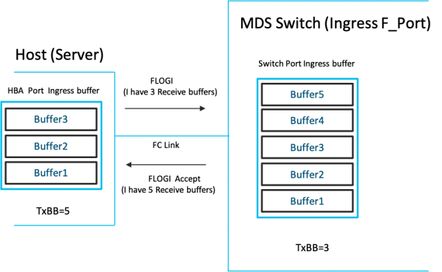
◉ During a FC link up, the number of receive buffers on a port is exchanged as B2B credits with its peer port (during FLOGI/ACC on a F-Port and ELP/ACC on a E-port). The transmitters at either ends set a TxBB counter = number of receive buffers on the peer port.

◉ An R_RDY primitive is used to indicate the availability of one buffer on the receive side of the port sending the R_RDY.

◉ As traffic starts flowing on the link, the R_RDY is used to constantly refresh the receive buffer levels to the transmitter. At the transmitter, every transmitted frame decreases TxBB counter by 1 and every R_RDY received from the peer increases the TxBB counter by 1. If TxBB counter drops to 0, no frame can be transmitted. Any frame needing to be sent has to wait till an R_RDY is received. At the receiver end, as and when incoming frames are processed and switched out, its ready to receive another frame and an R_RDY is sent back to the sender. This control loop constantly runs bidirectionally on every FC link. It ensures the transmit end of an FC port can transmit a frame only if the receiving port has a buffer to receive the frame.

Cisco DIRL, Cisco Tutorial and Material, Cisco Learning, Cisco Certification, Cisco Guides, Cisco Career
Figure 1: B2B crediting on an FC link
 
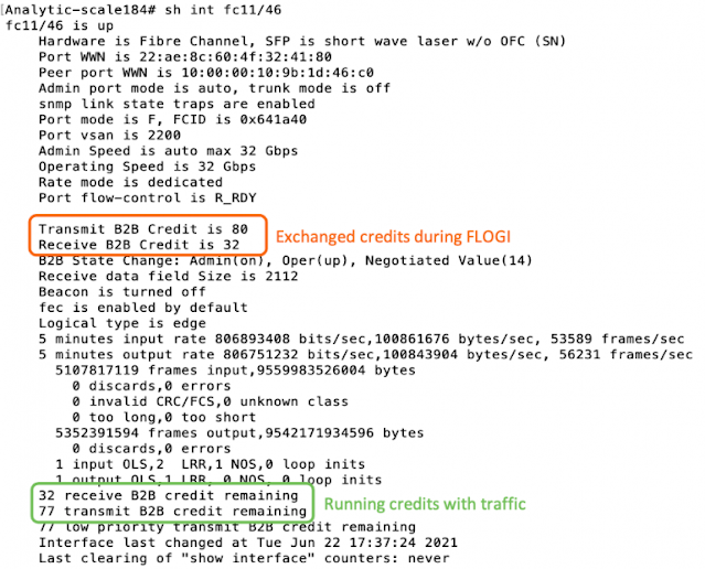
To see B2B crediting in action, take a look at a Cisco MDS switch that is switching traffic, and view the interface counters (Figure 2) that indicate the exchanged and live credits on a FC link.

Cisco DIRL, Cisco Tutorial and Material, Cisco Learning, Cisco Certification, Cisco Guides, Cisco Career
Figure 2: Cisco MDS show  interface command displays B2B credits

Insight: FC Primitives are single words (4 bytes) that carry a control message to be consumed at the lower layers of the FC stack. They are not FC frames and so transmitting a R_RDY itself does not require a credit. The R_RDYs are inserted as fill words between frames (instead of IDLEs) and so do not carry an additional bandwidth penalty either.

I hope I have touched upon just the enough of the basics to introduce you to two interesting concepts unique to Cisco MDS FC ASICs that forms the foundation of CISCO DIRL technology.

1. Ingress Rate Limiter

In the Cisco MDS FC ASICs, a frame rate limiter is implemented at the receiver side of port to throttle the peer transmitting to it. The rate limiter is implemented as a leaky bucket and can be enabled on any FC port. If you never heard this term before, please review the information at Wikipedia: Leaky bucket to learn more about this technology.

The ingress buffers on the port are treated like a leaky bucket and filled by a token when a full frame is received. At the same time the tokens are leaked from the bucket at a configurable rate of ‘R’. The rate ‘R’ is programmed based on a dynamically deduced rate by the Cisco DIRL software logic.

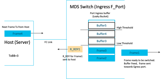
As the bucket leaks and the received frames are switched out, R_RDYs have to be sent to the peer. The sending of the R_RDY is tied to two bucket thresholds viz. Low and High threshold as follows:

◉ If bucket occupancy < Low Threshold, R_RDY is immediately sent out.

◉ If the bucket occupancy > Low Threshold and < High threshold, R_RDY is sent with credit pacing.

◉ If the bucket occupancy > High threshold, the R_RDY is held back and will be sent out when occupancy falls below the High threshold.

In summary, an R_RDY is sent out only if the bucket has ‘leaked enough’.

2. Credit pacing

When the buffer(bucket) occupancy hits the High threshold, all R_RDYs are stalled. Eventually the leak will cause the occupancy to fall below High threshold and all the pending R_RDYs will have to be sent out. This can result in a burst of R_RDYs sent to the peer which can result in a flood of waiting frames to be transmitted, which can again result in the buffer at the receiver port to go past the High threshold. This ‘ping-pong’ effect can result in very bursty traffic when traffic rates are high. To avoid this, R_RDY pacing is employed wherein a hardware timer paces out the release of R_RDYs such that incoming traffic is smoothed out while not exceeding the rate ‘R’.

By using ingress rate limiting and credit pacing on a port the Cisco MDS ASICs will ensure that a host/storage port is only able to send out frames at a rate <= ‘R’ on that port. The below diagrams illustrate the functioning of the scheme.

A. Port buffer occupancy is below the lower threshold

Cisco DIRL, Cisco Tutorial and Material, Cisco Learning, Cisco Certification, Cisco Guides, Cisco Career
Figure 3: Port buffer below Low threshold

B. Port buffer occupancy is above the high threshold

Cisco DIRL, Cisco Tutorial and Material, Cisco Learning, Cisco Certification, Cisco Guides, Cisco Career
Figure 4: Port buffer above High threshold

C. Port buffer occupancy is between Low and High threshold. Host can only send at rate <= R

Cisco DIRL, Cisco Tutorial and Material, Cisco Learning, Cisco Certification, Cisco Guides, Cisco Career

Figure 5: Port buffer between High and Low threshold with R_RDY pacing

Source: cisco.com