Saturday 19 March 2022

Cisco Radio Aware Routing

Cisco Radio Aware Routing addresses several of the challenges faced when merging IP routing and radio communications in mobile networks, especially those exhibiting ad hoc (MANET) behavior. This technology has applications in the defense industry as well as state and local government for search and rescue, law enforcement, and disaster assessment.

Looking at the Real-World Problem Description – Mesh Topology


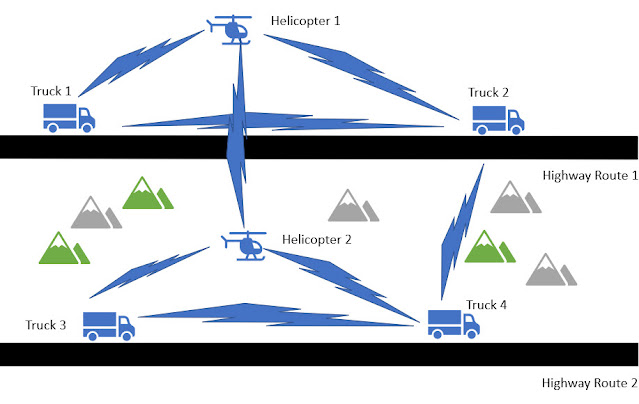
The above network is a voice, video, and data network between moving vehicles that consists of both ground and air vehicles. This mobile network is a peer-to-peer mesh that changes as topographical obstructions are encountered and is called “mobile ad hoc network” or MANET for short.


In the scenario shown above, all 4 trucks have a reliable, consistent connection with the helicopters flying over the same road. The two helicopters always have line of sight and will always have a connection between each other. The trucks may even be able to connect to the other helicopter or a truck on the opposite road when conditions are favorable. Here we see that the path between trucks 1 and 3 are completely blocked. The path between Truck 2 and 4 is about to be blocked.

Our existing routing protocols such as OSPFv3 and EIGRP need to adjust their path metrics very quickly to maintain a cohesive operational network. The routing protocol also needs a way to get information from the radios, requiring a radio to router protocol that is delivered by Cisco Radio Aware Routing in the form of two open protocols, which we will discuss here.

Cisco Radio Aware Routing provides capabilities that facilitate:

◉ Optimal route selection based on cross-layer feedback from cooperating radios

◉ Faster convergence when nodes join and leave the network

◉ Flow-controlled communications between the radio and its partner router

◉ Efficient integration of point-to-point, directional radio topologies with multihop routing

◉ Neighbor Up / Down Status

Here is a schematic view of a piece of the network:


What Are Underlying Technical Problems that Need to be Solved?


◉ Fluctuations in radio link quality affect throughput and need to be factored into route cost calculation.

◉ The self-forming, self-healing nature of a mobile ad hoc network requires immediate recognition of topology changes to help ensure fast convergence.

◉ Radios need to control the rate at which routers send information to minimize the need for queuing within the radio.

◉ Directional radios form point-to-point or point-to-multipoint networks with neighbors, which increases the size of the router’s database and reduces routing efficiency.

What Are the Benefits of Radio Aware Routing?


◉ Enables network-based applications and information to be delivered reliably and quickly over directional radio links.

◉ Provides faster convergence and optimal route selection so that delay-sensitive traffic, such as voice and video, is not disrupted.

◉ Reduces impact on radio equipment by minimizing the need for internal queuing/buffering; also provides consistent quality of service for networks with multiple radios. 

How Radio Aware Routing Works – Currently Two MANET Choices


Today, radios have 2 possible RAR protocols which are both supported in select Cisco routers:

1. RFC-5578 – PPP over Ethernet (PPPoE) Extensions for Credit Flow and Link Metrics

2. RFC-8175 – Dynamic Link Exchange Protocol (DLEP)

The actual choice of protocols is largely dependent on the radio vendor and the intended applications and optimization of their devices.

RFC 5578 and RFC 8175 provide an effective, cross-layer mechanism for communicating radio network status to IP routers – RFC 5578 primarily for Time Division Multiple Access (TDMA) style radios and RFC 8175 is primarily for multiaccess shared media radios that is very similar to WiFi. 

(1) RFC 5578 – PPP over Ethernet (PPPoE) Extensions for Credit Flow and Link Metrics

This solution, based on Internet Engineering Task Force (IETF) Request for Comments (RFC) 5578, employs PPP over Ethernet (PPPoE) sessions to facilitate intranodal communications between a router and a compliant device, such as a mobile radio or satellite modem. A PPPoE session is established between router and radio on behalf of every other router/radio neighbor. Once these PPPoE sessions are established, a PPP session is established end to end. This protocol is particularly suited for TDMA style radios.

Cisco Radio Aware Routing (RAR) using RFC 5578 is specifically targeted at routing over directional radio networks that are built with point-to-point links.

From the abstract of the RFC Document:

“This document extends the Point-to-Point Protocol over Ethernet (PPPoE) with an optional credit-based flow control mechanism and an optional Link Quality Metric report. These optional extensions improve the performance of PPPoE over media with variable bandwidth and limited buffering, such as mobile point-to-point radio links.”


◉ Neighbor Up/Down Signaling: Enables Cisco routers to provide faster network convergence by reacting to link status signals generated by the radio, rather than waiting for protocol timers to expire. The routing protocols (OSPFv3 or EIGRP) respond immediately to these link status signals by expediting adjacency formation or tear-down.

◉ Link Quality Metrics Reporting: The PPPoE protocol has been extended to enable a radio to report link quality metric information to a router. Cisco routers have been enhanced so that OSPFv3 or EIGRP routing protocols can factor link quality metrics into route cost calculations.

◉ PPPoE Credit-Based Flow Control: This PPPoE extension allows a receiver to control the rate at which a sender can transmit data for each PPPoE session, so that the need for queuing in the radio is minimized.


(2) RFC 8175 – Dynamic Link Exchange Protocol (DLEP)

DLEP is a control protocol between a router and a DLEP enabled radio MODEM. The DLEP message exchange between the router and radio allow the radio to tell the router about the link quality. This is somewhat analogous to the way the bar icon on your cell phone tells you about your WiFi or LTE signal quality.


From the abstract of the RFC Document:

“When routing devices rely on modems to effect communications over wireless links, they need timely and accurate knowledge of the characteristics of the link (speed, state, etc.) in order to make routing decisions. In mobile or other environments where these characteristics change frequently, manual configurations or the inference of state through routing or transport protocols does not allow the router to make the best decisions.  This document introduces a new protocol called the Dynamic Link Exchange Protocol (DLEP), which provides a bidirectional, event-driven communication channel between the router and the modem to facilitate communication of changing link characteristics.”

DLEP is better suited for multi-access shared media radios that are very similar to WiFi.

How Does DLEP Help?

◉ Without DLEP these are 2 equal cost paths to any unadjusted routing protocol.
◉ With DLEP routing metrics can be adjusted in real-time to favor the best path.
◉ With DLEP the radio network conditions reported can also be used in the router’s Quality of Service (QoS) traffic shaping decisions.
◉ With DLEP we have Neighbor Up/Down Status.


Atmospheric conditions and interference will ultimately favor one band vs. the other. While this example was simplified by only considering a point-to-point technology, DLEP is actually optimized for radio mesh topologies.

Why Cisco?


Cisco Radio Aware Routing is the industry’s first router-based implementation of RFC 5578 and RFC 8175. As the global leader in mission-critical networking and IP communications, Cisco is uniquely positioned to deliver reliable and efficient converged voice, video, and data solutions to organizations around the world. Cisco solutions are backed by award-winning technical support and advanced services.

Source: cisco.com

Thursday 17 March 2022

Unified Software Tracing Comes to Cisco IOS XE – It’s Unified, Binary, Streaming, and Highly Scalable

Software tracing is essential for Cisco’s team of enterprise networking software engineers, along with the legions of developers, systems admins, and tech support personnel among our customers. Tracing is the specialized use of logging to capture the operational behavior of code down to the code execution path. It’s indispensable for developers for troubleshooting network software in production to catch bugs, errors, misconfigurations, or other problems throughout the birth and lifecycle of products.

Cisco has provided a more efficient and effective way to use network software traces at scale for our 80+ enterprise platforms. It’s called unified tracing.

With unified tracing, all traces deployed in software running anywhere in the system (e.g., in line cards or other field replaceable units [FRUs]), are streamed to the main processor of the Cisco device and collected in a single set of files. This integration of trace messages provides time-ordered, real-time visibility into what a router, switch, wireless controller, or Internet of Things (IoT) device is doing across its approximately 100 processes.

Here’s how we’ve ramped up tracing in a big way and what it means for enterprise networking.

Tracing Gets Binary in Cisco IOS XE 16.0

Release 16.x introduced binary tracing to the Cisco IOS XE code base. It’s now widely used.

Binary tracing relies on compiler technology to assist in the encoding of each trace point, allowing for the storage of non-ASCII text objects, like packets and software-generated objects in the trace stream. These binary objects provide richer operational information about how network platforms are performing.

Fully distributed, binary tracing also enables tracing on steroids, with some Cisco enterprise platforms able to exceed peak trace rates of two million traces per second per process. It also separates the encoding of high-performance traces from the decoding of traces, which can be displayed to users later.

Unified Tracing introduced in Cisco IOS XE Release 17.7

With binary tracing alone, each process writes traces independently to separate files. If you have 100 processes, you have 100 separate sets of files, which slows down troubleshooting.

With unified tracing, all trace files for a system are merged into one trace file set of messages with all of the information about their origins (Figure 1). Each trace event uniquely identifies the calling site information and carries context to know where in the system and the source code it was produced.

Cisco IOS XE, Cisco Exam Prep, Cisco Tutorial and Materials, Cisco Guides, Cisco Career, Cisco Learning, Cisco Skills, Cisco Jobs
Figure 1. From Per-Process Binary Trace Files (BTF) to Unified Trace Files (UTF) and Messages

Users can filter the time-ordered unified trace messages to make intelligent filtering decisions and see and understand what’s going on in the 100 or so processes at work in each device with greater detail and in real-time. You might notice a large number of errors coming from a single process with unified tracing. Then you can inspect the code and quickly understand what’s going on. Before, reviewing individual trace files one at a time made this process much slower and not scalable.

Developers don’t have to change a single line of code to enjoy the improved logging performance of unified tracing. They can also continue to use the Buginf API as their Cisco IOS XE debug trace command. The goal was to introduce a uniform way to log information throughout a system regardless of the source, avoiding expensive data transformations or duplicate information logged in different ways for different customers.

Features and Benefits of Unified Tracing


◉ Automated traces from 100+ processes are streamed in real-time, in temporal order, across FRUs to a centralized set of unified trace files

◉ Centralized trace inspection based on high-rate filtering in real time is now possible―an industry first

◉ Richer information is collected on bugs, errors, misconfigurations, etc., across all system processes

◉ Identification of software issues during development and for post-release troubleshooting is accelerated

Additionally, in a coming version of unified tracing, trace files can be exported for use by analytical frameworks to provide further trace inspection and improve troubleshooting and insights. It’s a brand-new feature that also will allow for more efficient use of device disc space because of current CPU limits on the number of traces that can be created. It will enable more traces to be created and the ability to retain trace files elsewhere for the life of a system.

More Meaningful, Scalable Traces


With unified tracing in Cisco IOS XE, customers get a lot more information about what’s happening in their Cisco network devices than ever before. Developers can use unified tracing to finetune performance. Systems administrators and tech support agents can use it for more detailed, faster, and more scalable troubleshooting.

At Cisco we’re continually investing in products to improve the troubleshooting and serviceability of our products and unified tracing is a prime example.

Source: cisco.com

Tuesday 15 March 2022

Randomized and Changing MAC (RCM)

What is Randomized & Changing MAC (RCM)

Historically wireless clients associate to the wireless network using the manufacturer assigned mac address that is associated with the wireless network interface card (NIC). This manufacturer-assigned mac address, which is globally unique, is also known as burn-in address (BIA). Use of this burn-in address everywhere raises the question of end-user privacy as the end-user can be tracked with WIFI’s mac address. In this document, this will be referred to as normal mac (address), in contrast to the random mac (address).

To improve end-user privacy, various operating system vendors (Apple iOS 14, Android 10 and Windows 10) are enabling the use of the locally administered mac address (LAA), also referred to as the random mac address for WIFI operation. When wireless endpoint is associated with random mac address, the MAC address of the endpoint changes over time.

The random mac address was limited to probe for known wireless networks. This is now expanded to association to the wireless networks. While this works well for the privacy of the end-user, it brings unique challenges to the Enterprise IT admin, who has been depending so far on the unique endpoint identity as the basis for driving policies. This will also affect different WIFI deployment models e.g., Guest, BYOD (Bring Your Own Device) and location analytics, etc. which rely on the uniqueness of the mac address.

To address and alleviate the issues due to the usage of random MAC addresses in the existing wireless deployments, Cisco provides an RCM solution.

Fig #1: RCM Cisco Solution

Random Mac Identification and Client access


Cisco solution Identifies the random mac usage and provides visibility for easy detection of issues and troubleshooting on WLC and Cisco DNA Center.

Cisco Catalyst 9800 can classify the device on the network using its Universally administered address (BIA) or Locally administered address (RCM) which helps administrators to distinguish between both mac addresses. Random MAC address is identified by a bit which gets set in the OUI portion of a MAC address to signify a locally administered address. The below picture depicts how to identify the locally administered mac address.

Fig #2: Random MAC Identification

In addition, Cisco 9800 wireless controller also provides the ability to control the client joining WIFI Network using RCM address. This is enabled through a configuration option to allow/deny RCM clients. When this configuration is enabled, then any client using the randomized changing MAC RCM (Locally administered MAC address) will not be able to join that wireless network.

MDM (Mobile Device Manager)/ISE BYOD Integrations:


MDM solution provides a unique device identity when the mac address of the device is randomized and changing. When the endpoint connects to the network using randomized MAC address, MDM compliance check and other security controls fail because of unrecognized random MAC addresses as device identifiers. This solution provides a unique identity to the device based on EAP-TLS which is known as DUID (Device Unique ID) solution.

◉ This solution relies on the MDM (Mobile device manager also referred to as Device managers, Unified Endpoint Managers (for example Ms Intune, Mobile Iron) which manage devices in an enterprise infrastructure.

◉ ISE provides the provisioning of the device with the device’s unique ID-based (DUID) certificates.

◉ The device presents this certificate during TLS based authentication ISE authorizes the devices and also reads the unique ID from the certificate.

◉ The device unique ID (DUID) is used for compliance check with MDM servers and also a unique identifier of the device in the endpoint table.

◉ The randomized MAC will not matter as now the device has a DUID using the ID in the cert.

◉ Since ISE has the mapping of the DUID and the random MAC and it can share this information in two ways
     
     ◉ Through pxGrid as part of session information where Cisco DNA Center is the pxGrid subscriber.
     ◉ WLC gets the client info from ISE as part of VSA access-accept, this info is sent to the Cisco DNA Center.

Fig #3: Device Unique ID MDM Flow

The same use case can be implemented through ISE as part of BYOD workflow as ISE can generate DUID during the BYOD process.

DNA Center visibility, Troubleshooting, Usage tracking for RCM


Fig #4: DNA Center RCM Client Dashboard
 
Using Cisco DNA Center, we will be able to track, troubleshoot and see where the random macs are being used in the network. For the devices using random mac addresses, Cisco DNA Center has introduced a new icon in front of the device MAC address to symbolize RCM. Cisco DNA Center users can filter the devices with mac address as an RCM address for the IT admin to track how many clients are RCM clients in the network.

Below Cisco DNA Center screen shows the filtered RCM Clients for visibility, tracking, and troubleshooting.

Users can see the visibility of the client DUID and random MAC and also which another mac address is related on Cisco DNA Center as shown in the below in Cisco DNA Center Client 360 page.

Fig 5: DNAC RCM Client 360 View

Fig 6: DNA Center RCM Client Details

Cisco DNA Center also shows if clients are not associating to the network because Random MAC is configured not to join the network. Below client screen shows that.

Fig 7: DNA Center RCM Client Association Failure View

Future of Random MAC Solution


Cisco will pursue with IETF to have a formal working group for MAC address device identification for Network and Application Services.

Source: cisco.com

Sunday 13 March 2022

Introducing the new ‘Defending Against Critical Threats’ report

Today, we’re pleased to launch our annual Defending Against Critical Threats report. Inside, we cover the most significant vulnerabilities and incidents of 2021, with expert analysis, insights and predictions from our security and threat intelligence teams across Cisco Talos, Duo Security, Kenna Security, and Cisco Umbrella.

It’s clear that 2021 – and, indeed, the start of 2022 – has been very challenging for security defenders. To bring our Defending Against Critical Threats: Analyzing Key Incident Trends report to life, I sat down with six expert threat hunters and analysts from these teams, and asked them to tell me about their findings on one specific cybersecurity threat, or incident, from the past 12 months. Each expert chose to discuss a topic which tells us a lot about the current priorities of threat actors – below you’ll find a brief summary on some of the key themes we covered.

We also conducted a survey among 190+ security and technology leaders via PulseQA to gauge their perspectives on the current threat landscape. We found that 66% of respondents felt that the complexity and volume of cybersecurity attacks had escalated in 2021, whilst 36% felt that attacks had stayed consistent with the previous year.

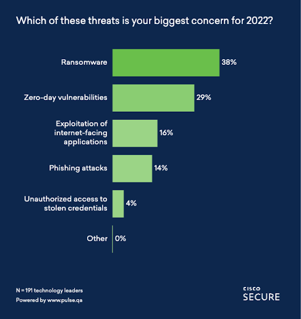
In the survey, we also asked about the top threat concerns security leaders had for 2022. Ransomware came in as the top concern, with 38% of respondents choosing that option. In the report, we discuss the evolution of ransomware and how it has reached a critical level for certain bad actors, provoking a more severe and structured governmental response. You’ll read about this in Matt Olney’s (Talos’ Director of Threat Intelligence and Interdiction) section about the Colonial Pipeline attack.

Cisco Prep, Cisco Exam Prep, Cisco Tutorial and Materials, Cisco Career, Cisco Skills, Cisco Jobs

Matt’s section also discusses supply chain attacks, which as Matt says, is one of the most challenging types of threats we face today. Forty-three percent (43%) of our Pulse respondents told us that they were impacted in a supply chain attack in 2021. Be sure to check out this section for advice on how to make your organization a smaller target for attackers.

Zero-day vulnerabilities came in as the second biggest concern for security practitioners, according to our survey. The report discusses the impact of Log4j with Talos’ Incident Response Practice Lead Liz Waddell, and how it has continued to cause an impact in 2022. Liz also provides a detailed seven-point action plan on how to deal with future zero-day attacks.

Additionally, we also look at the most impactful disclosed vulnerabilities of 2021 with Jerry Gamblin, Kenna’s Director of Security Research (now part of Cisco). This section is particularly helpful for defenders who wish to move to a more predictive-based, prioritized vulnerability management plan.

You’ll also read about  the impact of Emotet in Artsiom Holub’s (Senior Security Analyst for Cisco Umbrella) section. Emotet is a very powerful loader that came back from the dead in 2021 to cause a lot of destruction, and the signs are that it has some very nefarious plans for 2022.

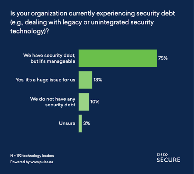
Dealing with legacy or unintegrated security technology, or ‘security debt,’ is a topic we are very passionate about helping our customers to combat, and in this report, our Advisory CISO Dave Lewis discusses why it’s becoming an increasing target of opportunity for cyber criminals. We asked  respondents if they were dealing with security debt and to what extent; the overwhelming majority (75%) said they were – but it was manageable. Unfortunately, 13% said that it’s a huge issue for them. Dave’s section contains plenty of advice on how to address this issue in your organization.

Cisco Prep, Cisco Exam Prep, Cisco Tutorial and Materials, Cisco Career, Cisco Skills, Cisco Jobs

Finally, for readers interested in reading about a day in the life of a Talos threat hunter, you’ll no doubt find Ashlee Benge’s section on the rise of macOS malware very thought-provoking.

The expert analysis you’ll read in this report highlights the crucial role of our defenders, and the capabilities that we, as an industry, have built based on the meticulous study of past attacker behavior.

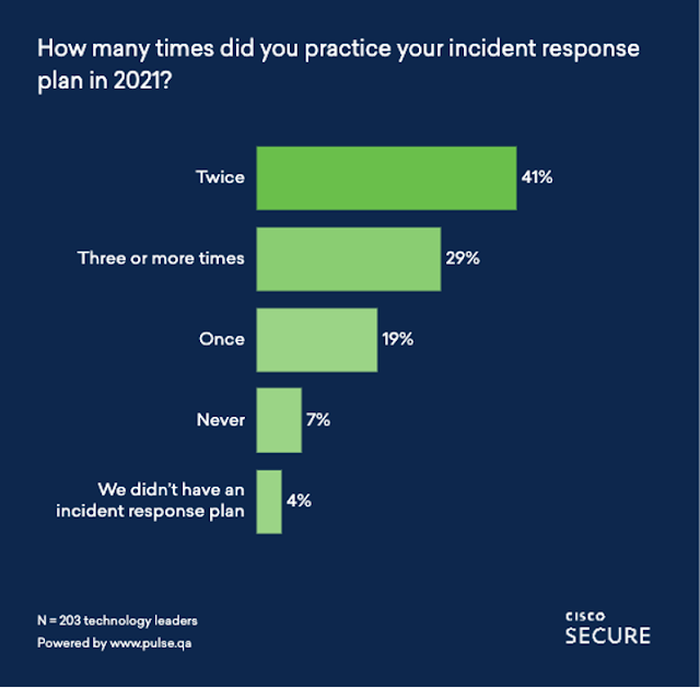
The good news is that according to our Pulse respondents, the majority of cybersecurity professionals undertake regular incident response testing. Forty-one (41%) are testing their plans twice a year, and 29% are testing more than three times a year. Only 4% said they didn’t have an incident response plan in place.

Cisco Prep, Cisco Exam Prep, Cisco Tutorial and Materials, Cisco Career, Cisco Skills, Cisco Jobs

If you’re a security defender looking to prioritize your focus areas and address patterns of concern, we hope that this year’s report will be helpful to you. It was put together by a dedicated group of security leaders, whose job it is to spot key incident trends.

Here’s what we cover in the new Defending Against Critical Threats:


◉ Colonial Pipeline: Moving Beyond Ransomware Thoughts and Prayers with Matt Olney, Director of Threat Intelligence and Interdiction, Cisco Talos

◉ Security Debt: An Increasing Target of Opportunity with Dave Lewis, Advisory CISO, Cisco Secure

◉ The Most Critical Vulnerabilities (You Might Not Be Thinking About) with Jerry Gamblin, Director of Security Research, Kenna Security (now part of Cisco)

◉ Log4j and How To Plan for Zero-Days with Liz Waddell, Practice Lead, Cisco Talos Incident Response

◉ What’s Emotet Doing Now? with Artsiom Holub, Senior Security Analyst, Cisco Umbrella

◉ The Rise of macOS Malware with Ashlee Benge, Lead, Strategic Intelligence and Data Unification, Cisco Talos

Source: cisco.com

Thursday 10 March 2022

Focus on HyperFlex: Sizing A New Cluster Using the Sizer and Profiler Tools

In this ‘Focus on HyperFlex’ blog, we’ll zero-in on different aspects of the Cisco HyperFlex (‘HX’) hyperconverged system and ways to make HX work best for you and your organization. This edition will illustrate on how to size a cluster when you might not have all the details of the workload worked out. In this situation, HyperFlex Profiler is the right approach to learn more about the workloads.

During my time in sales, teams often asked me to size a HyperFlex cluster and provide a customer quote. It was customary to have many more questions than the team or customer could answer about the application. Normally, they would provide me with an Excel sheet with some CPU and memory values. That is a great start, and it gave me deep insight into the customer’s application. However, an application profile is not only about averages of CPU and memory.  There are several more parameters needed, including the performance and latency peaks. With the customer’s permission, I would run a HyperFlex Profiler in their environment to gain more information about their application. Before installing the OVA on their vCenter, I would explain what HyperFlex Profiler is and how it helps with sizing their new HyperFlex environment. 

HyperFlex Profiler 

If there is no historical insight into the potential clustered application environment, then start with HyperFlex Profiler. HyperFlex Profiler will gather data on the vCenter environment and consolidate that mass of data to a single, easily digestible file. This file will quickly size the cluster after importing it into the HyperFlex Sizer tool and paint a clearer picture of the environment and workloads. 

However, profiling the environment is not a quick hit in a short period of time. The best approach is to run the HyperFlex Profiler for at least seven days or, preferably, 30 days. A longer measuring period ensures you capture data when “end of the month reports” are run. Of course, don’t just measure the environment during a weekend when there is little traffic! Be sure to capture at least one logical business cycle for that application. 

The HyperFlex Profiler is an OVA installed on a VMware environment. The only configuration is to provide (read-only) access to the vCenter environment and define which servers the HyperFlex Profiler will monitor. Multiple servers and/or clusters can be selected. For environments running different types of workloads, it is recommended to isolate them by selecting the servers in their environments – for instance, the VDI or the SQL environment. Of course, selecting all servers and workloads is also an option. Keep in mind that you will have more overhead this way. 

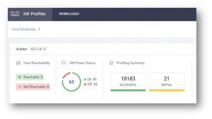
When it is monitoring the environment, you will see the following: 

Focus on HyperFlex, Cisco Preparation, Cisco Learning, Cisco Career, Cisco Skills, Cisco Jobs, Cisco Exam Preparation

More details about the environment can be shown in other tables and graphics, that can be exported in pdf format. 

It is essential to see the peaks of the environment. This way, you can make sure the new HyperFlex designed cluster can handle the workload, and ensure there is room for expansion. 

Focus on HyperFlex, Cisco Preparation, Cisco Learning, Cisco Career, Cisco Skills, Cisco Jobs, Cisco Exam Preparation

There are different graphs in the HyperFlex Profiler. Here you can see the metrics of the storage reads. Here, you have more insight into the frequently used block-size of the environment. This is one of them:

Focus on HyperFlex, Cisco Preparation, Cisco Learning, Cisco Career, Cisco Skills, Cisco Jobs, Cisco Exam Preparation

The next step is to use the power of the HyperFlex ProFiler to create a bill of material out of all the information from vCenter.  The data of the HyperFlex Profiler can be manually or automatically downloaded and uploaded to the HyperFlex Sizer. 

HyperFlex Sizer 


The HyperFlex Sizer is an online tool (https://hyperflexsizer.cloudapps.cisco.com/) accessible to both partners and customers. With this tool, you can add your personal, most commonly used workloads to a HyperFlex cluster and have the sizing tool decide the best option. HyperFlex Sizer takes the HyperFlex best practices into account when calculating the optimal solution. 

Furthermore, you can customize the sizing tool, using only the preferred components the customer wishes to see in the new HyperFlex environment. Different elements, like CPU, memory, types and sizes of drives, and more, can be customized. 

Uploading the data of the HX Profiler to the HX Sizer is entirely straightforward. After claiming the HX Profile into the HX Sizer, the tool will produce a practical Bill of Materials that can be the baseline of a  discussion with your partner about the best solution for your applications. 

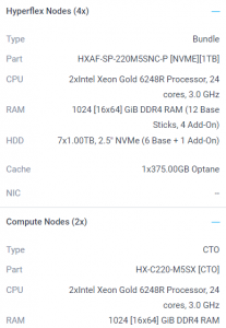
Here is a screenshot of the HyperFlex Sizer where a HyperFlex cluster is calculated with the requested workload:

Focus on HyperFlex, Cisco Preparation, Cisco Learning, Cisco Career, Cisco Skills, Cisco Jobs, Cisco Exam Preparation

A variation of HyperFlex clusters may be advised. This is possible when you want to have different workloads, each with their characteristics. 

It shows the amount of HyperFlex or compute nodes, what type of nodes and  includes all the parts that are needed to create the solution. This way, you don’t have to configure everything manually, eliminating human errors.  

Create an estimate


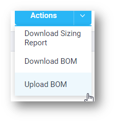
Once you know the total size of the new HyperFlex cluster, partners or Cisco experts can easily upload the Bill of Material to Cisco Commerce Workspace (CCW) and estimate the HyperFlex cluster.

Focus on HyperFlex, Cisco Preparation, Cisco Learning, Cisco Career, Cisco Skills, Cisco Jobs, Cisco Exam Preparation

In CCW, the estimate can be converted to an order.

Source: cisco.com

Tuesday 8 March 2022

EIS in Transition: Impacts on Digital Transformation for Federal Networks

For Federal agencies, Enterprise Infrastructure Solutions (EIS) has provided a comprehensive, solution-based method to address their IT telecommunications and infrastructure needs. Over the years, EIS has seen many changes that directly impact stakeholders. But its primary purpose as a key driver for the digital transformation of enterprise telecommunications and networking solutions remains unchanged. Yet many agencies, such as Networx and WITs, face contract expirations on May 31, 2023. To maintain momentum for digitization, Federal agencies must begin the transition now by strategically mapping how and where it should start.

What’s next for Federal Digital Transformation?

For decades, Cisco has built a strong relationship with the U.S. Federal Government. Our portfolio of products, solutions, and services provide Federal agencies with the critical technology and support they need to enable the transformation of their networks within the EIS contract.

By leveraging these existing contracts, agencies are reducing costs and acquisition time. They’ve been able to digitize aging systems and catch-up to the private sector in capabilities. But now what? Which direction should Federal agencies go as they transition contracts within EIS? The simple answer: Cisco SD-WAN.

Beyond EIS with SD-WAN

Cisco SD-WAN is the premier choice for replacing expensive and aging legacy WAN. Federal agency networks leveraging Cisco’s SD-WAN solution can benefit from:

◉ Enhanced user experience

◉ Reduced costs

◉ Simplified operations

◉ Improved performance

◉ And robust security.

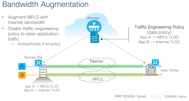
Cisco SD-WAN enables more efficient bandwidth allocation, powering critical applications to faster, smoother performance. This capability is now a necessity as Federal agencies move to cloud services and witness an explosion of app-wielding users connecting remotely.

Cisco Prep, Cisco Tutorial and Material, Cisco Career, Cisco Skills, Cisco Job, Cisco Preparation, Cisco Learning

Wi-Fi6 for the Federal Government


The transition in EIS contracts also provides Federal agencies with the opportunity to rethink their adoption of new and emerging technologies. One example is Wi-Fi 6. It builds on earlier Wi-Fi standards to provide Gigabit Ethernet Access – but with the reliability and predictability that comes from a licensed radio.

Cisco Wi-Fi 6 Solutions let users of modern, more agile networks benefit from new capabilities while connecting wirelessly. Cisco’s Wi-Fi 6 gives access points the power to support more clients in dense environments, plus it provides a better experience for users of typical wireless LAN networks.

Partnering for the future of EIS


In late 2021, the General Services Administration (GSA) issued a Request For Information (RFI) seeking comments to modify the EIS contract so that agencies can more quickly obtain mobility-as-a-service (MaaS) offerings (starting in late 2022). This expansion of EIS would allow for the use of 5G and bring the benefits of edge compute to the government workforce.

At Cisco, we’re also planning to provide additional capabilities to the U.S. Government, including 5GaaS capabilities. This could be a game-changer, enabling the U.S. Government to take advantage of mobility services.

Cisco Prep, Cisco Tutorial and Material, Cisco Career, Cisco Skills, Cisco Job, Cisco Preparation, Cisco Learning

For Federal agencies, the transition in EIS contracts provides a unique opportunity to leverage innovative technologies that can maximize network agility and security while enhancing workforce productivity.

At Cisco, we understand this and are helping shape the future of government with products, solutions, and services that empower agile networks, enhanced collaboration, and a holistic security approach. By preparing now, your agency can leverage the upcoming EIS transition to help shape that future.

Source: cisco.com

Monday 7 March 2022

Cisco 300-435 ENAUTO | Syllabus | Exam Overview | Questions | Study Guide


Cisco ENAUTO Exam Description:

The Automating and Programming Cisco Enterprise Solutions v1.0 (ENAUTO 300-435) exam is a 90-minute exam associated with the CCNP Enterprise, Cisco Certified DevNet Professional, and Cisco Certified DevNet Specialist - Enterprise Automation and Programmability certifications. This exam tests a candidate's knowledge of implementing Enterprise automated solutions, including programming concepts, Python programming, APIs, controllers and automation tools. The course, Implementing Cisco Enterprise Automation Solutions, helps candidates to prepare for this exam.

Cisco 300-435 Exam Overview:

Related Study Guide:-